Ventilation device

a technology of ventilation device and fan, which is applied in the direction of space heating and ventilation details, air heaters, domestic heating details, etc., can solve the problems of difficult cleaning, contaminated dust collecting surfaces, and inability to dampen sound ducts, so as to reduce the fan output of ingoing air

Inactive Publication Date: 2006-03-21
STENEBY BENGT +1
View PDF18 Cites 20 Cited by
  • Summary
  • Abstract
  • Description
  • Claims
  • Application Information

AI Technical Summary

Benefits of technology

[0014]a device that is favourable from environmental point-of-view, i.e., it should consume small amounts of energy;
[0016]a device without leakage between ingoing and outgoing air, and which does not transfer odours or other substances between rooms;
[0021]a device that does not spread imbalance in airflows to other rooms;
[0022]a device that can also be driven by low voltage in order to simplify installation (does not require certification) and reduce electrical interference fields;
[0030]The ventilation device according to the invention is primarily intended to be used in residences, schools, day care centres, etc., but it can also, e.g. together with solar panels, be adapted for ventilation of mobile spaces, such as caravans, work sheds, etc., since the power requirements of the device per m2 of ventilated air is very low. During use in buildings, several ventilation devices may be interconnected through their control units to form large co-operating systems. The ventilation device is also suitable for use in buildings equipped with a conventional ventilation system, but with need of further ventilation, e.g., during reconstruction. Since the volumes of outgoing and ingoing air are equal, this means that the ventilation apparatus does not disturb the rest of the ventilation system.

Problems solved by technology

Further, the ducts need to be sound dampened, partly because of overhearing between rooms through the air terminal devices and the duct system, and partly due to the sounds that are generated by fans and to the sounds arising in the usually strictly controlled air terminal devices.
The facilities are equipped with filters against dust and small particles, but they still get contaminated and have to be cleaned.
Further, dust-collecting surfaces, which are difficult to clean, arise through such installations.
In addition to this are the costs of the electrical power facility for the ventilation device.
However, the regulation of airflows in said document is limited in direct connection to the unit, and within the unit.
It does not guarantee a balanced flow of air into each room.
A further drawback of this ventilation system according to prior art is the bypass-arrangement, which allows outgoing air to flow across to the ingoing side, which means pollution of the ingoing air.
Internal leakage in heat-exchangers is another problem in large systems with an extensive flap system, which may allow leakage between ingoing and outgoing air.
Consequently, there are no readable values which can regulate the output of the fan when the outdoor and indoor temperatures are the same or similar, i.e. in the interval where no heat exchange takes place.
The difficulty, so far, has been to scale down the dimensions sufficiently to house the heat-exchanger and the control equipment within the short duct defined by the thickness of the wall.

Method used


Image

  • Ventilation device
  • Ventilation device
  • Ventilation device

Examples


Embodiment Construction

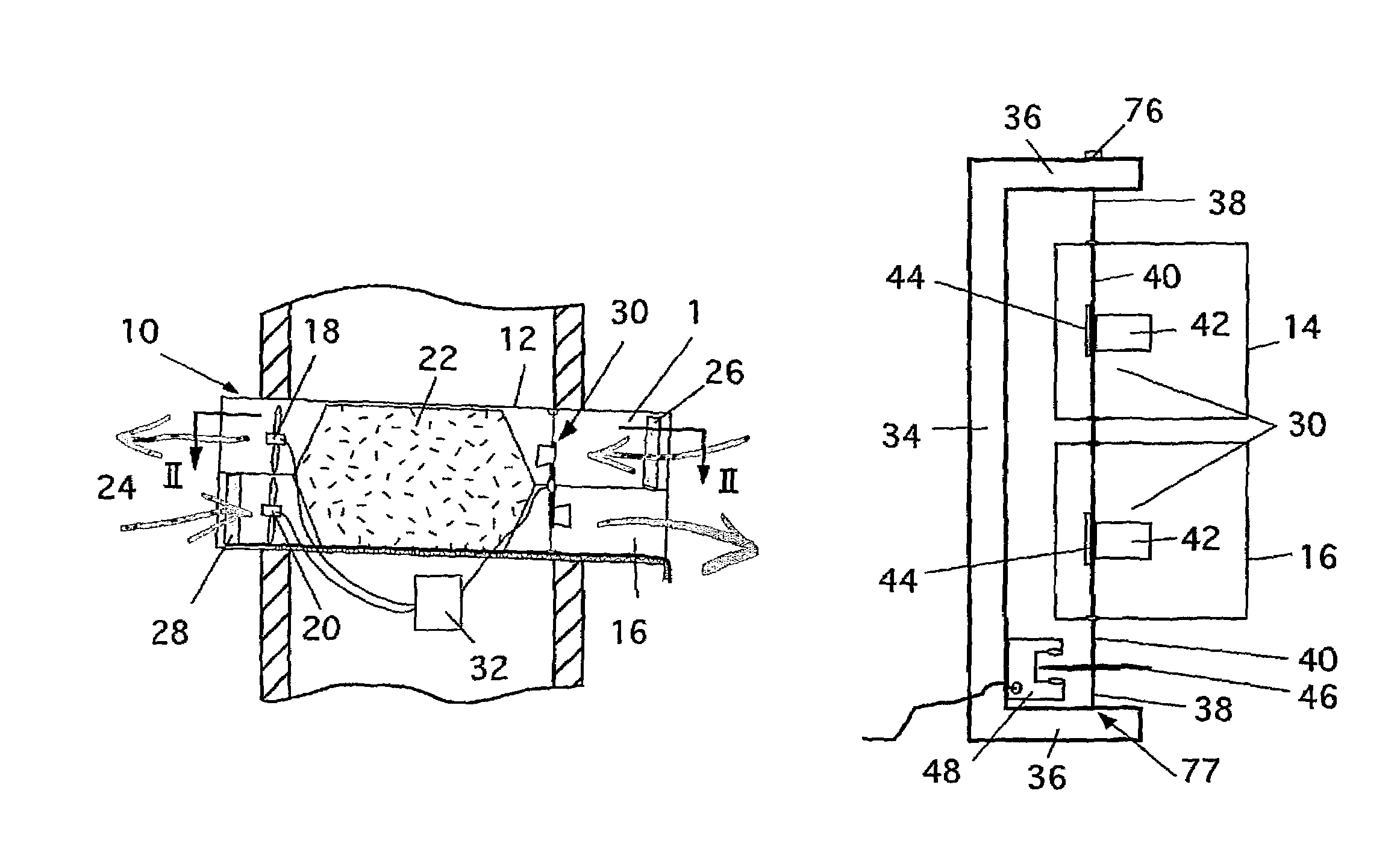
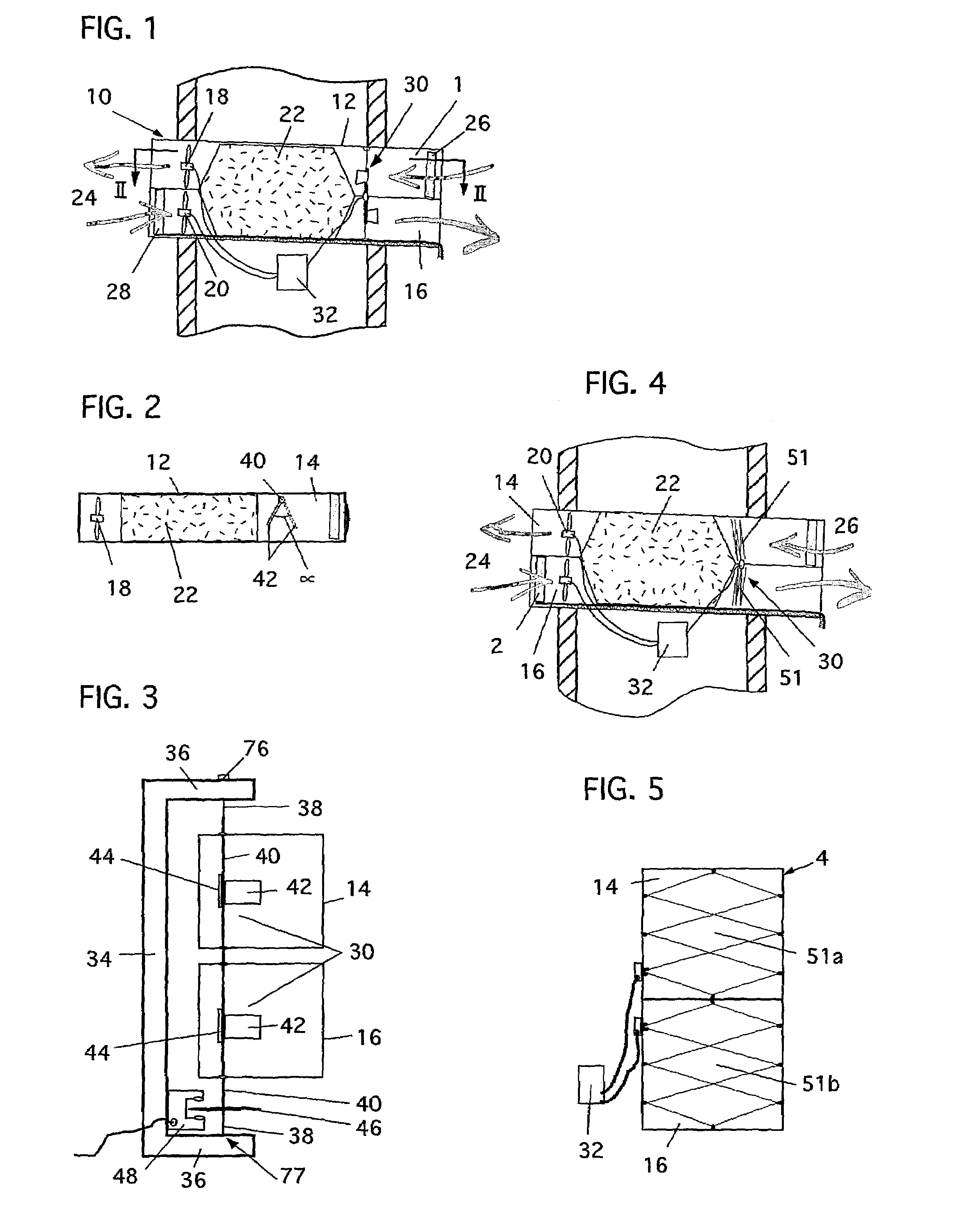
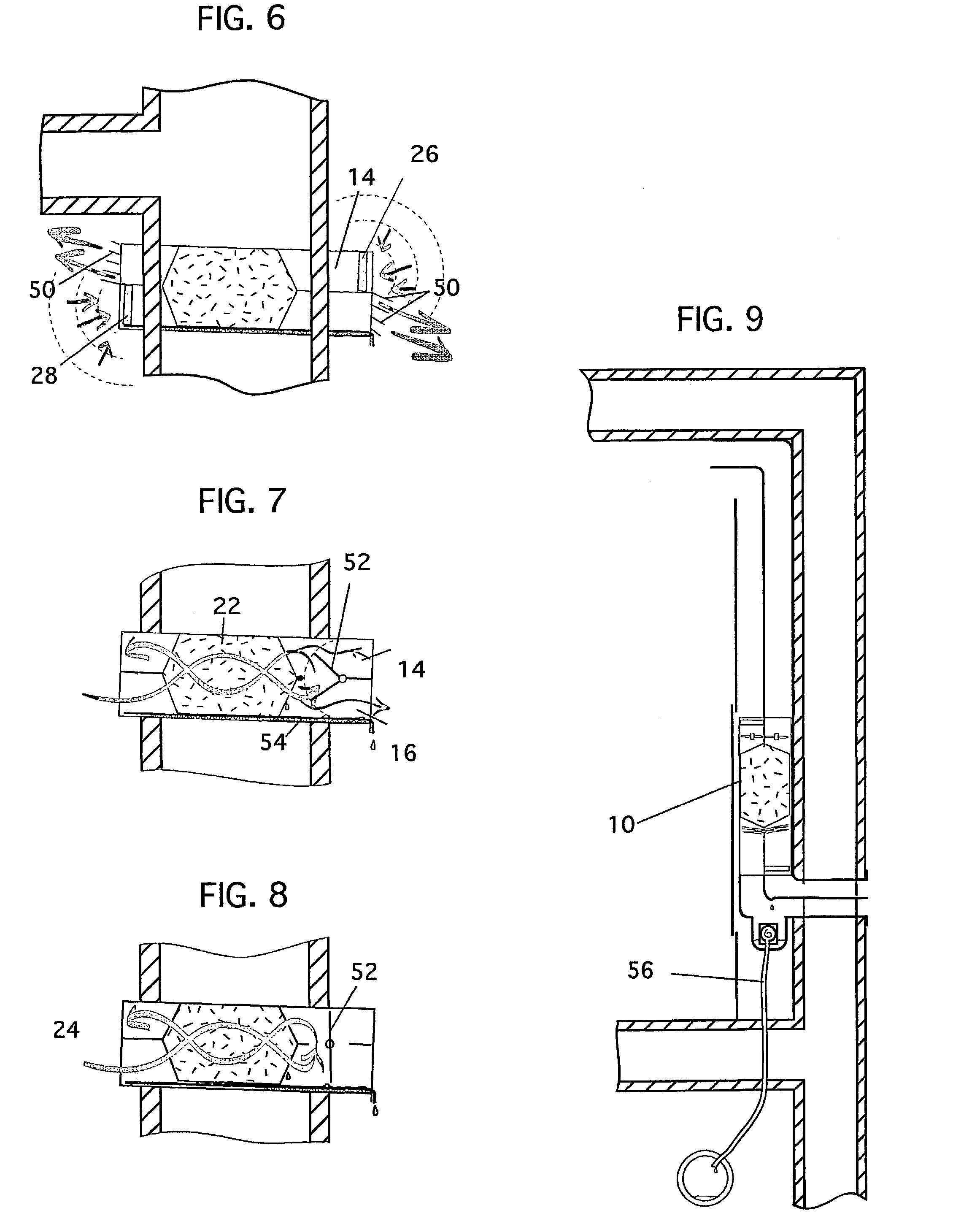
[0053]The ventilation device of the invention, denoted 10 in the drawings, is, according to FIGS. 1 and 2, constituted of a casing 12, an ingoing air duct 14, leading ingoing fresh air, and an outgoing air duct 16, leading used outgoing air. In each of the ducts a fan 18, 20 is arranged. Centrally in the casing, a heat-exchanger 22 of counter flow type is arranged, i.e., the heat-exchanger is divided into parallel passages, of which every second passage leads the ingoing air, and every other second passage leads the outgoing air in counter flow to and from the room 24, respectively. In the inlet of the respective channels 14, 16, a filter 26, 28 is placed, and in both channels a sensor 30, e.g., an instrument for the measurement of the amount of air flowing through each respective duct, is arranged. The instrument is connected to a control means 32 for controlling the velocity of the fans, so that the amount of air ventilated from the room 24 is substantially equal to the ingoing ai...


PUM


Abstract

The invention relates to a ventilation device for ventilation room by room and / or zone by zone and comprises: a) a device casing (12), which is provided in or adjacent an outer wall of a building or the like and which connects room air to outside air, b) a heat-exchange (22) of counter flow type, provided in the casing (12) and transferring heat from the outgoing and in-going airflows, respectively, c) two fans (18,20) arranged in said casing (12), of which one is connected to the ingoing air duct (14) of the heat-exchanger (22) and the other to the outgoing air duct (16) of the heat-exchanger (22), d) at least one sensor (30) for determination of the airflow's relative deviation in velocity from a neutral value of the airflows passing through each respective duct (14, 16), and e) a control means (32), which, depending on the values given by the sensor (30), is arranged to regulate the rotation speed of the fans (18, 20), for the purpose of substantially balancing the airflow, so that it is substantially equal for the ingoing and outgoing air.

Description

[0001]The present invention relates to a ventilation device for ventilation room by room and / or zone by zone, and which comprises a heat-exchanger of counter current-type, transferring heat from the ingoing and outgoing airflows.BACKGROUND OF THE INVENTION AND THE PROBLEM[0002]Generally, ventilation facilities consist of large, centrally positioned and centrally controlled, assemblies with large energy demands, and with an extensive system of ducts for ingoing and outgoing air. The duct system branches off towards the locations of consumption, where preadjusted air terminal devices control the amount of air that a room is expected to require. The air ducts often cross fire cells, and in these cases they are generally equipped with automatic fire valves. Further, the ducts need to be sound dampened, partly because of overhearing between rooms through the air terminal devices and the duct system, and partly due to the sounds that are generated by fans and to the sounds arising in the ...

Claims


Application Information

Patent Timeline
Patent Type & Authority Patents(United States)
IPC IPC(8): F24F7/007F24F7/08F24F11/00F24F12/00
CPCF24F11/0079F24F12/006Y02B30/563Y02B30/746F24F2011/0038F24F2110/30F24F11/77Y02B30/56Y02B30/70
Inventor STENEBY, BENGTMATTSSON, TORSTEN
Owner STENEBY BENGT
Why Eureka
Try Eureka