
Warpage control method and apparatus

Inactive Publication Date: 2006-03-21
HARRISON DOUGLAS W
View PDF5 Cites 9 Cited by
  • Summary
  • Abstract
  • Description
  • Claims
  • Application Information

AI Technical Summary

Benefits of technology

[0007]The invention provides post shipment arrangement for maintaining stacks of lumber under compression to avoid or correct warpage as the stacks of lumber are sold piece by piece and the stacks of lumber are reduced form a normal stack to irregular pieces or boards whereby the retailer prevents or corrects warpage of the remainder of the stacks of lumber as it is being sold piece by piece.
[0009]The method of avoiding or correcting warpage of lumber in stacks includes utilizing several frameworks formed in the shape of a rectangle or square which defines an interior periphery with channels to guide a pair of compression mechanisms in transverse paths for applying compressive force on the stacks of lumber even for irregular stacks by utilizing filler blocks with the stacks of lumber to provide a square or rectangular shape within the interior periphery thereby providing uniform compressive force on the remaining pieces of lumber in the stacks of lumber.
[0010]The method of maintaining irregular stacks of lumber under compressive force to avoid or correct warpage of the individual pieces of lumber remaining in a stack of lumber which has been un-banded for sale of some of the lumber in the stack to retail customers that includes providing a framework in the form of a rectangular or square including force applying mechanisms supported from two adjacent sides of the framework for compressing lumber extending within and between two such frameworks to simulate a piece of lumber so the force applying mechanism evenly distributes the compressive force.

Problems solved by technology

Thus, the lumber making up the stacks is subjected to the environment without the metal bands surrounding it thus permitting warpage to some extent.
It is apparent such a technique is only successful in avoidance or correction of lumber warpage while the bands or metals strips remain in place.

Method used


Image

  • Warpage control method and apparatus
  • Warpage control method and apparatus
  • Warpage control method and apparatus

Examples


Embodiment Construction

)

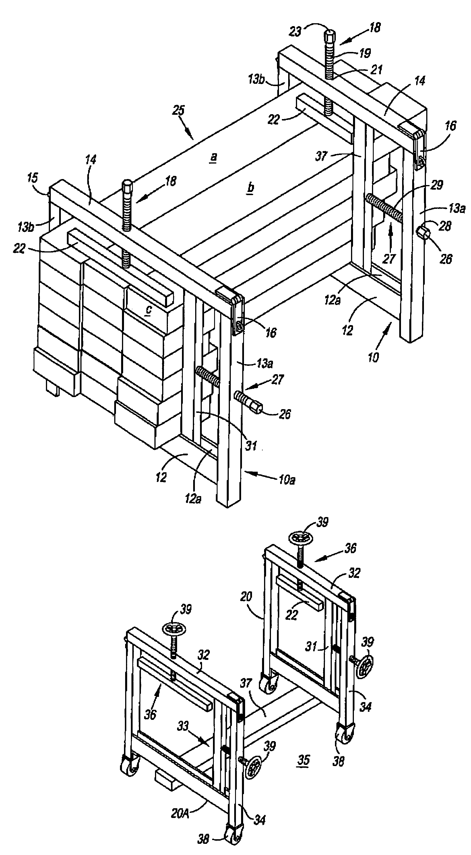
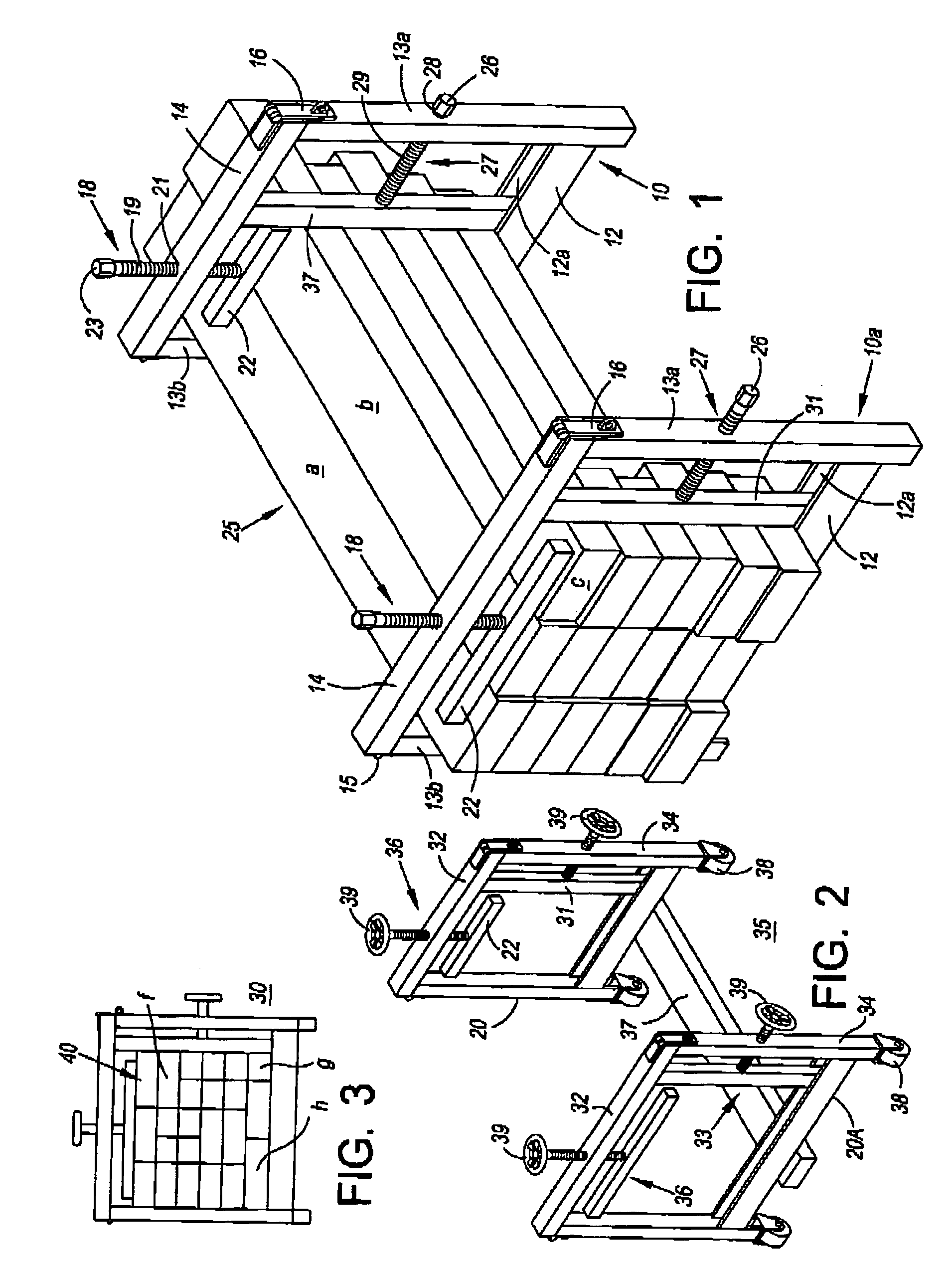
[0020]Referring now to the drawings and in particular FIGS. 1 through 3, frameworks 10 and 10a include base 12, side posts 13a and 13b, and top14 having hinge 15 and latch 16. Force mechanism 18 is mounted in top 14 and includes screw 19 with head 23 threaded in aperture 21 and connected to flat member 22 by a loss motion coupling. Upon rotating head 23 of screw 19, flat member 22 transversely engages boards a and b of lumber stack 25. Force mechanism 27 includes screw 29 with head 26 threaded in aperture 28 of side post 13a and connected to flat member 31 by loss motion coupling. Base 12 of framework 10 has channel 12a which guides flat face member 31 against board b and those stacked under board b to apply force on stack 25 to the sides of the boards. Framework 10a is similar to framework 10 but slightly larger. It has base 12 with channel 12a, top 14 with force mechanism 18, and side posts 13a and 13b with force mechanism 27 the same as framework 10. Filler block c and those sta...


PUM


Abstract

Method and apparatus for storing stacks of lumber to avoid or correct warpage utilizing two or more rectangular or square frameworks, open throughout which may include linkage for maintaining a fixed spacing of the frameworks and / or rollers for mobility in handling the stacks of lumber. A side of each framework may be hinged for opening and include a latch mechanism for securing such side from opening. Two adjacent sides of each framework each mount a force actuator having a flat face member supported within the interior periphery of each framework for engagement with the exposed surface of the stacks of lumber positioned within and extending between the two or more frameworks which upon activation of the force actuator squeezes the stack of lumber in two directions, thereby avoiding or correcting warpage during storage of the stacks of lumber. Further, where the stack of lumber does not present a uniform exposed adjacent surfaces filler blocks are used to provide such surfaces initially or whenever a price of lumber is removed from the stack.

Description

BACKGROUND OF THE INVENTION[0001]1. Field[0002]This invention relates to a system of storing stacks of lumber under compressive force to avoid or correct warpage. In more detail, the system includes providing several open frameworks for use in compressing regular or irregular stacks of lumber. The frameworks are spaced at predetermined distances apart depending on the condition of the lumber being stored.[0003]2. State of the Art[0004]In the past, lumber is generally shipped in stacks and held tightly bound by metals straps or ribbon that encircle the stack of lumber. In this fashion, the metal straps tend to retain newly milled lumber in a flat or un-warped condition. Once the stack of lumber is in storage by the retailer, the metal straps are removed to accommodate sales to customers and no retention force is provided to the stacks of regular or irregular seasoned or unseasoned lumber. Thus, the lumber making up the stacks is subjected to the environment without the metal bands su...

Claims


Application Information

Patent Timeline
IPC IPC(8): B25B27/14
CPCB25B5/003B65D19/385B25B5/10B25B5/006
Inventor HARRISON, DOUGLAS W.
Owner HARRISON DOUGLAS W
Learn More