Conduit system

a technology of connecting elements and ducts, applied in the direction of dowels, furniture joining, rod connections, etc., can solve the problems of entailing a great deal of trouble, and achieve the effect of avoiding the positioning of the connecting element over a considerable distan

Inactive Publication Date: 2006-03-21
NEDERLANDSE ORG VOOR TOEGEPAST-NATUURWETENSCHAPPELIJK ONDERZOEK (TNO)
View PDF9 Cites 32 Cited by
  • Summary
  • Abstract
  • Description
  • Claims
  • Application Information

AI Technical Summary

Benefits of technology

[0006]The foregoing object is achieved by providing a fastening element which passes through a connecting element and has a clamping piece which can be inserted into a recess and fixed in the recess by turning. This means that the connecting element is put in place and fixed directly at the point at which it is also to be fixed to the profile. Arduous insertion or complicated shifting and positioning of the connecting element over a considerable distance is avoided. Furthermore, the connecting element can be fixed in a substantially more specific manner.
[0008]The clamping piece is preferably a small plate shaped like a parallelogram. This small plate has the advantage that, during rotation in the undercut groove, for example, it strikes the groove walls and therefore cannot be rotated further. The width of the small plate is of course limited to the width of the groove or is less than the latter, specifically in order that this small plate can be inserted into the groove without difficulty.
[0021]In order that a predefined position or a predefined course of the profile can be taken into account, there should be a plurality of recesses in the loadbearing leg, so that the fastening element passes through the loadbearing leg at different points. For example, the obvious thing here is a diagonal slot or a slot parallel to the side. Furthermore, it is possible to provide a hole as a transition to a slot, the hole having a diameter which is larger than the diameter of the bolt head. In this way, a fastening element can even be inserted into the slot subsequently, without having to take it apart.

Problems solved by technology

This has the disadvantage that the connecting plates or the like have to be introduced and positioned arduously or, often, have to be shifted along the profile from a far removed point which, for example in the case of overhead work, entails a great deal of trouble.

Method used


Image

  • Conduit system
  • Conduit system
  • Conduit system

Examples


Embodiment Construction

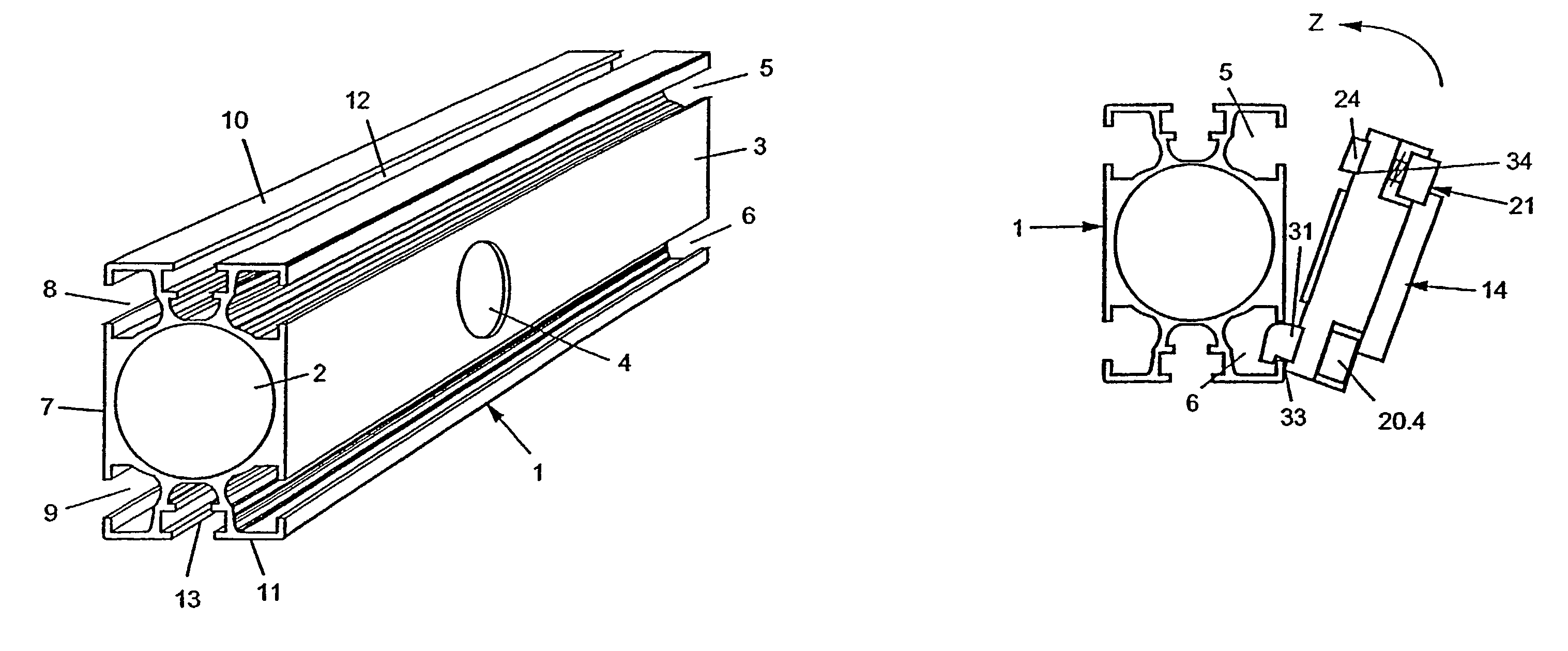
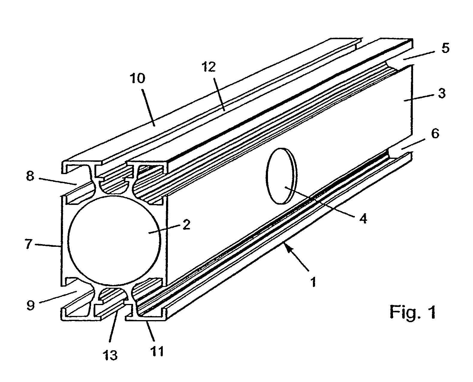
[0044]A conduit system according to the invention for supplying, conducting and distributing fluids, in particular air, is to be composed in a modular fashion from individual profiles, as far as possible of the same design. The exemplary embodiment shown in FIG. 1 of a profile 1 has a longitudinal channel 2, in which the fluid is carried. In an outer wall 3 of the profile 1 there is an opening 4, through which fluid can be removed by means of an appropriate connecting element 14.

[0045]Furthermore, it can be seen that, in the outer wall 3, two undercut grooves 5 and 6 running parallel to each other are integrally molded, which serve to fix a connecting element 14 described in the following figures.

[0046]In this exemplary embodiment of a profile 1, it can be seen that an outer wall 7 lying opposite the outer wall 3 is also provided with respectively two further undercut grooves 8 and 9, while an upper side 10 and a lower side 11 in each case only have one groove 12 and 13. Of course, ...


PUM


Abstract

A conduit system for supplying, conducting and distributing fluids, especially air, comprising profiles, which have a longitudinal channel for the fluid and, in at least one outer wall, at least one recess for receiving a fastening element for a connecting element. The fastening element passes through the connecting element and comprises a clamping piece which is inserted into a recess and fixed in the recess by turning.

Description

BACKGROUND OF THE INVENTION[0001]The invention relates to a conduit system for supplying, conducting and distributing fluids, especially air, comprising profiles which have a longitudinal channel for the fluid and, in at least one outer wall, at least one recess for receiving a fastening element for a connecting element.[0002]Conduit systems of this type are known in many and various forms and designs. They are used, for example, to conduct liquids, but primarily to conduct air and here in particular to conduct compressed air to desired removal points.[0003]G 91 02 781.0 U1, for example, discloses a hollow rail or rod generally used to conduct or channel and distribute fluids, which consists of extruded profile material made of aluminum and has a central longitudinal bore and flute-like or channel-like grooves extending laterally in the longitudinal direction and open to the outside. With the aid of connecting elements, this rail or rod can be detachably connected, in modular fashio...

Claims


Application Information

Patent Timeline
Patent Type & Authority Patents(United States)
IPC IPC(8): F16L39/00F16L9/00
CPCF16L9/003Y10T403/55Y10T403/4671F16B2200/205
Inventor KAISER, CHRISTOF
Owner NEDERLANDSE ORG VOOR TOEGEPAST-NATUURWETENSCHAPPELIJK ONDERZOEK (TNO)
Why Eureka
Try Eureka