Dielectrophoretic systems without embedded electrodes

Inactive Publication Date: 2006-03-21
NAT TECH & ENG SOLUTIONS OF SANDIA LLC
View PDF15 Cites 59 Cited by
  • Summary
  • Abstract
  • Description
  • Claims
  • Application Information

AI Technical Summary

Benefits of technology

[0007]The electrodes necessary to generate an electric field, rather than being disposed directly in the fluid flow channels as in prior art devices, can be placed in relatively remote fluid reservoirs that are in fluid communication with the flow channels. Placing electrodes in reservoirs is convenient because: 1) the effects of electrolytic bubble generation that can block narrow fluid flow channels are minimized; 2) electrochemical changes in pH and conductivity are minimized; 3) while not located directly in the flow channel itself, as in prior art dielectrophoretic devices, the electrodes can still be used

Problems solved by technology

The use of insulating structures to create a non-uniform electric field obviates the need for the complex and difficult-to-fabricate arrays of prior art embedded electrodes.
Moreover, the us

Method used


Image

  • Dielectrophoretic systems without embedded electrodes
  • Dielectrophoretic systems without embedded electrodes
  • Dielectrophoretic systems without embedded electrodes

Examples


Embodiment Construction

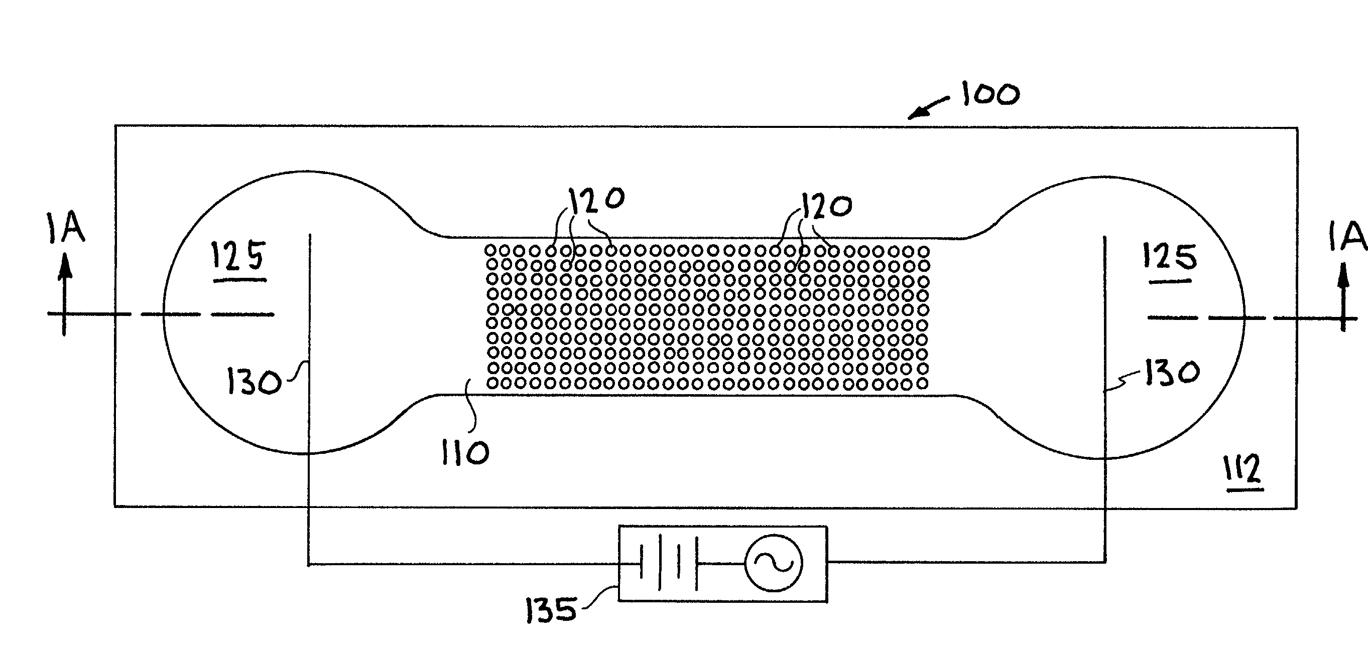
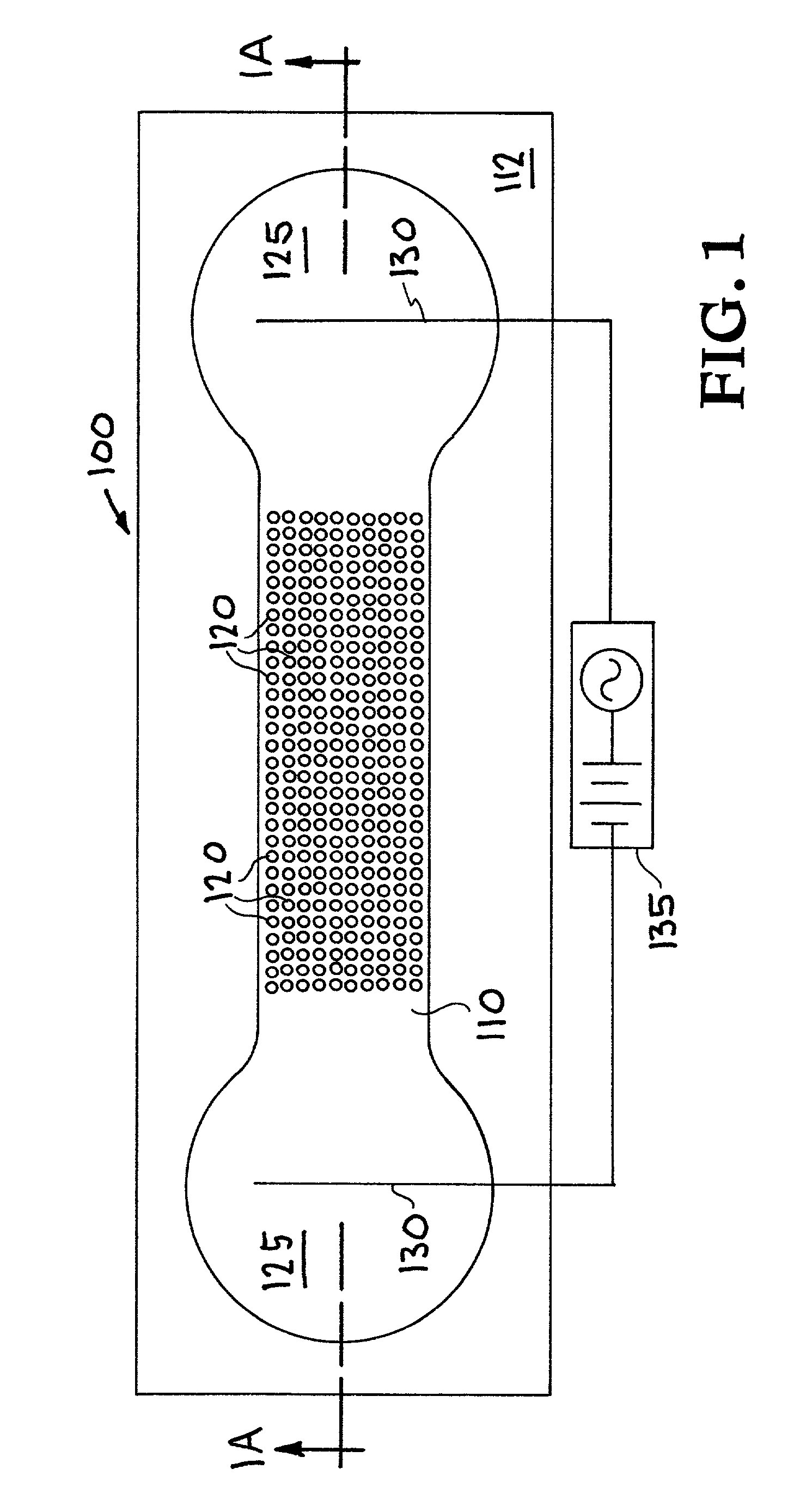
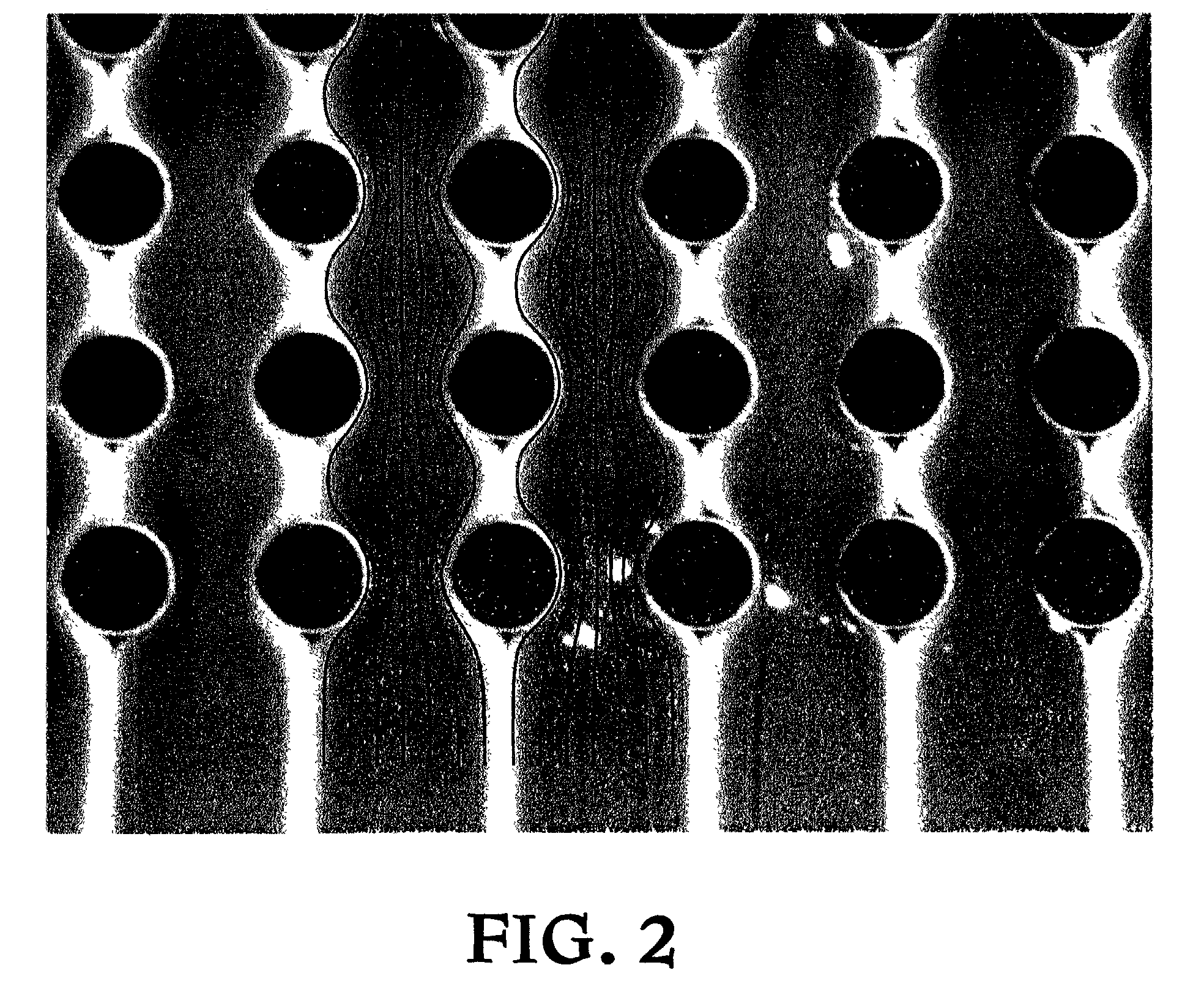
[0020]The present invention is directed to the use of a plurality of insulating structures arranged within a flow channel of a device for dielectrophoretic separation of particles, wherein the arrangement can be uniform or nonuniform. These insulating structures provide the non-uniform electric field required for the dielectrophoretic separations and replace the embedded electrode structures of conventional devices.

[0021]Hereinafter, and throughout the written description of the invention the terms “dielectrophoretic” and “dielectrophoresis” will be abbreviated as DEP, for convenience. The term “particle” is understood to stand for biological as well as non-biological matter generally that can be in the size range of from about 5 nm to 200 μm, such as proteins, DNA, RNA, assemblages of molecules, viruses, plasmids, bacteria, cells or assemblages of cells, protozoans, embryos, or other small organisms, minerals, crystals, colloids, and gas bubbles. The term “spatial separation” is us...


PUM

PropertyMeasurementUnit
Pressureaaaaaaaaaa
Flow rateaaaaaaaaaa
Shapeaaaaaaaaaa

Abstract

Method and apparatus for dielectrophoretic separation of particles in a fluid based using array of insulating structures arranged in a fluid flow channel. By utilizing an array of insulating structures, a spatially inhomogeneous electric field is created without the use of the embedded electrodes conventionally employed for dielectrophoretic separations. Moreover, by using these insulating structures a steady applied electric field has been shown to provide for dielectrophoresis in contrast to the conventional use of an alternating electric field. In a uniform array of posts, dielectrophoretic effects have been produced flows having significant pressure-driven and electrokinetic transport. Above a threshold applied electric field, filaments of concentrated and rarefied particles appear in the flow as a result of dielectrophoresis. Above a higher threshold applied voltage, dielectrophoresis produces zones of highly concentrated and immobilized particles. These patterns are strongly influenced by the angle of the array of insulating structures with respect to the mean applied electric field and the shape of the insulating structures.

Description

STATEMENT OF GOVERNMENT INTEREST[0001]This invention was made with Government support under contract no. DE-AC04-94AL85000 awarded by the U. S. Department of Energy to Sandia Corporation. The Government has certain rights in the invention.CROSS-REFERENCE TO RELATED APPLICATIONS[0002]Not applicable.BACKGROUND OF THE INVENTION[0003]The present invention is directed to method and apparatus for dielectrophoresis that eliminates the use of conventional embedded electrodes and substitutes in their place insulating flow structures that create spatially inhomogeneous electric fields that effect dielectric transport. Further, the use of these flow structures provides for dielectrophoretic separations by means of steady applied electric fields, applied alternating electric fields, or combinations thereof.[0004]Electrokinesis and dielectrophoresis are two technologically important particle and fluid transport mechanisms in microscale flow channels. In the former, particle or fluid transport is...

Claims


Application Information

Patent Timeline
IPC IPC(8): C25B11/00C25B13/00B03C5/02G01N15/02
CPCG01N15/0266B03C5/026B03C5/005
Inventor CUMMINGS, ERIC B.SINGH, ANUP K.
Owner NAT TECH & ENG SOLUTIONS OF SANDIA LLC
Why Eureka
Try Eureka