
Filtration and plug drain device for containing oil and chemical spills

a technology of oil and chemical spills and drain devices, which is applied in gravity filters, water/sludge/sewage treatment, loose filtering materials, etc., can solve the problems of hydrocarbon contamination of surface water with hydrocarbons, hydrocarbon contamination of rain and meltwater runoff, and inadvertent introduction of hydrocarbons and other chemicals into the environment, so as to optimize the response of the filter/plug drain assembly

Active Publication Date: 2006-03-21
PETRO BARRIER SYST
View PDF49 Cites 17 Cited by
  • Summary
  • Abstract
  • Description
  • Claims
  • Application Information

AI Technical Summary

Benefits of technology

"The present invention provides an apparatus and method for preventing the discharge of hydrocarbons and other contaminants into the environment, by removing the contaminants from a water stream when they are present in normal unavoidable low levels, and plugging the flow stream when the contaminants are present in abnormal high levels. The invention includes a filter / plug drain assembly with filtering, filtering / plugging, and plugging material, as well as a plurality of spacer elements that form two distinct flowpaths, an annular flowpath outside of the tubes and a central flowpath within the tubes. The user can choose the desired filtering, filtering / plugging, or plugging material and provide alternative / complementary flow paths to optimize the response of the filter / plug drain assembly to different contaminants."

Problems solved by technology

There is growing concern about the inadvertent introduction of hydrocarbons and other chemicals into the environment, and the contamination of surface water with hydrocarbons.
Hydrocarbon contamination of rain and meltwater runoff is a problem in a variety of situations, including: in parking lots and on roadways due to leaks of oil and fuel from vehicles; on rooftops having coatings that release hydrocarbons in warm weather; and in containment areas for electrical transformers, oil tanks and other facilities where large quantities of hydrocarbons are stored or used.
It is not uncommon for such containment areas to be subject to minor ongoing spills of oil and other hydrocarbons due to minor leaks, servicing of equipment etc.
Such containment areas may also be subject to large spills of several thousand gallons of oil or other hydrocarbons.

Method used


Image

  • Filtration and plug drain device for containing oil and chemical spills
  • Filtration and plug drain device for containing oil and chemical spills
  • Filtration and plug drain device for containing oil and chemical spills

Examples


Embodiment Construction

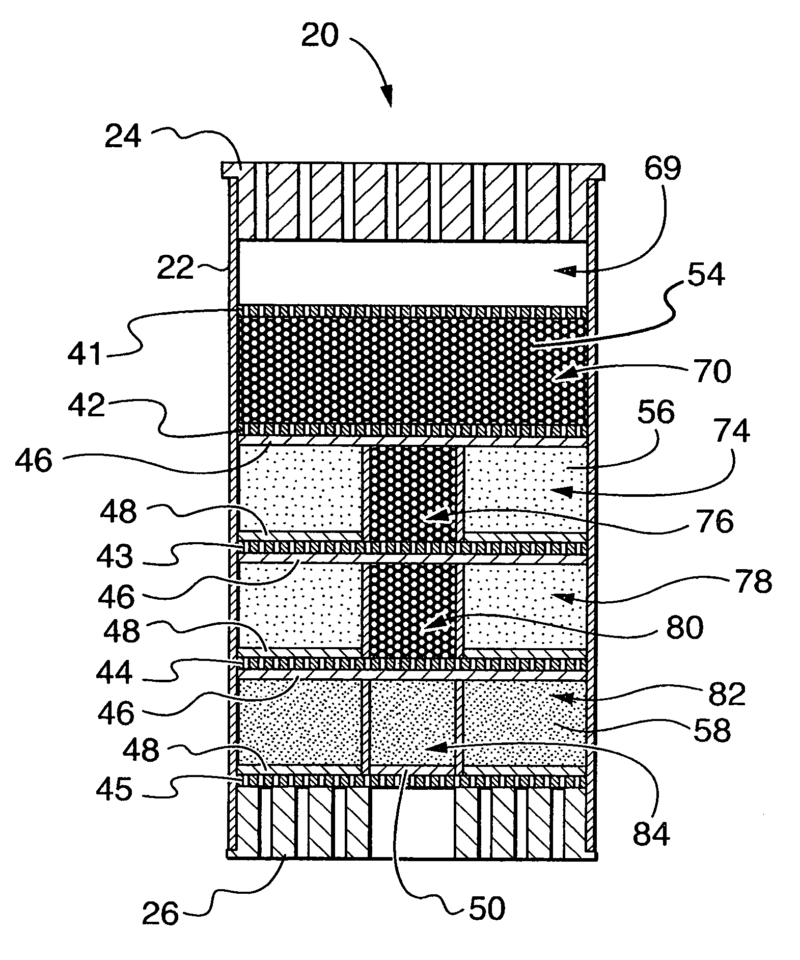
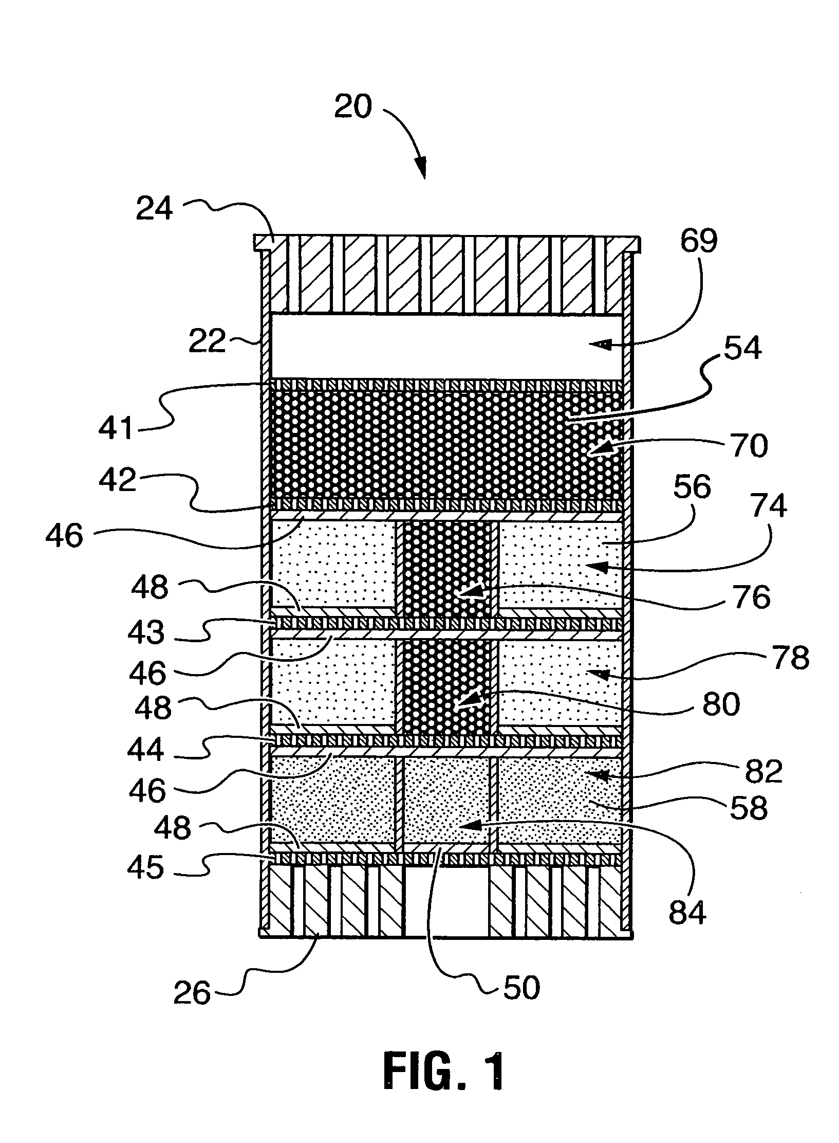
[0033]FIG. 1 shows a schematic sectional view of a filter / plug drain insert 20 suitable for insertion into a floor drain (not shown) for removing small amounts of a target contaminant from the drain water and plugging the drain when the drain water contains an amount of the target contaminant in excess of the contaminant removal capacity of the filter / plug drain insert 20.

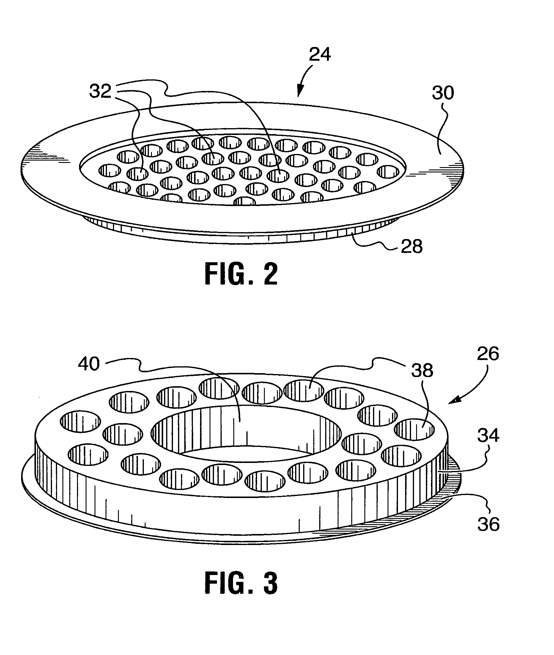
[0034]The filter / plug drain insert 20 includes a drain body 22, a lid 24 (shown in FIGS. 1 and 2) and an exit grate 26 (shown in FIGS. 1 and 3). Although the embodiments and components described herein and shown in the drawings are described and shown with the filter / plug drain insert 20 oriented vertically with the lid 24 at the top and the exit grate 26 at the bottom, the filter / plug drain insert 20 and the other embodiments described herein need not be oriented vertically. The filter / plug drain insert 20 and other embodiments may be used in any orientation and are expected to function as intended so long as in u...


PUM

PropertyMeasurementUnit
hydrophobicaaaaaaaaaa
lipophilicaaaaaaaaaa
areasaaaaaaaaaa

Abstract

A filter / plug drain assembly for insertion into a drain so as to prevent the passage of selected contaminants through the drain is disclosed. The filter / plug assembly includes stacked layers of filter, filtering / plugging and plugging material. The filter / plug assembly has alternative internal flowpaths configured to provide different plugging speeds when exposed to ongoing low levels of selected contaminants.

Description

CROSS-REFERENCE TO RELATED APPLICATION[0001]This application claims the benefit of U.S. Provisional Patent Application No. 60 / 562,242, filed 15 Apr. 2004.FIELD OF THE INVENTION[0002]This invention relates to a filtration and plug drain device for containing spills of hydrocarbons and other chemicals. More specifically, this invention relates to a device for use in a water drain for separating hydrocarbons from the drain water and for plugging the drain when the quantity of hydrocarbons exceeds the hydrocarbon removal capacity of the device, as with a hydrocarbon spill or leak.BACKGROUND OF THE INVENTION[0003]There is growing concern about the inadvertent introduction of hydrocarbons and other chemicals into the environment, and the contamination of surface water with hydrocarbons.[0004]Hydrocarbon contamination of rain and meltwater runoff is a problem in a variety of situations, including: in parking lots and on roadways due to leaks of oil and fuel from vehicles; on rooftops havin...

Claims


Application Information

Patent Timeline
Patent Type & Authority Patents(United States)
IPC IPC(8): C02F1/28E03F5/16B01D24/00B01D25/02B01D35/04B01D39/16C02F1/00C02F1/40C02F1/68E03F1/00
CPCB01D24/008E03F5/16B01D35/04B01D39/16C02F1/285E03F1/00E03F5/0404B01D25/02C02F1/001C02F1/28C02F1/283C02F1/681C02F2101/32C02F2103/001C02F2301/043
Inventor MUIR, IAINBARRETT, FIONA ELIZABETH
Owner PETRO BARRIER SYST
Learn More