Battery pack and rechargeable vacuum cleaner

a battery pack and vacuum cleaner technology, applied in the field of battery pack and rechargeable vacuum cleaner, can solve the problems of lithium ion secondary batteries, li metal dendrites are likely to grow in a short time, safety problems, etc., and achieve the effect of improving the cycle characteristi

Inactive Publication Date: 2006-03-21
KK TOSHIBA
View PDF12 Cites 51 Cited by
  • Summary
  • Abstract
  • Description
  • Claims
  • Application Information

AI Technical Summary

Problems solved by technology

The reason is that dendrite of metal is likely to precipitate on the negative electrode of the LIB when charging and discharging of large current are repeated, and precipitates of lithium dendrite may reach up to the positive electrode through the separator, thereby causing internal short-circuit, which leads to a safety problem.
Accordingly, when charged or discharged at high rate, dendrite of Li metal is likely to grow in a short time, especially on the negative electrode.
Owing to this reason, the lithium ion secondary battery is not used in high rate discharge applications, and hence is cannot be applied in products consuming a large current such as a cordless cleaner, a robot, a UPS, and an electric-assisted bicycle.
Hence, when this cooling device is used for cooling the lithium ion secondary battery, long life is not expected in the charging and discharging cycles for discharging at high rate.

Method used


Image

  • Battery pack and rechargeable vacuum cleaner
  • Battery pack and rechargeable vacuum cleaner
  • Battery pack and rechargeable vacuum cleaner

Examples


example 1

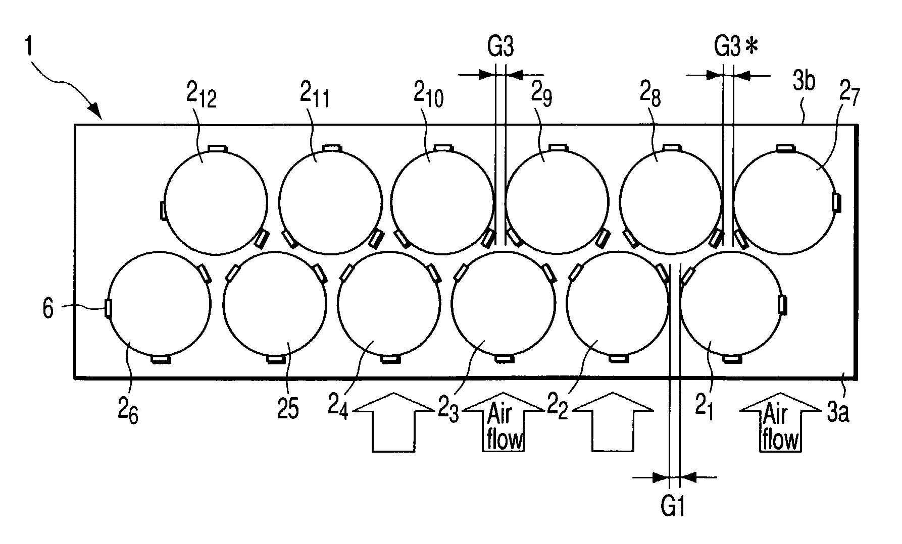
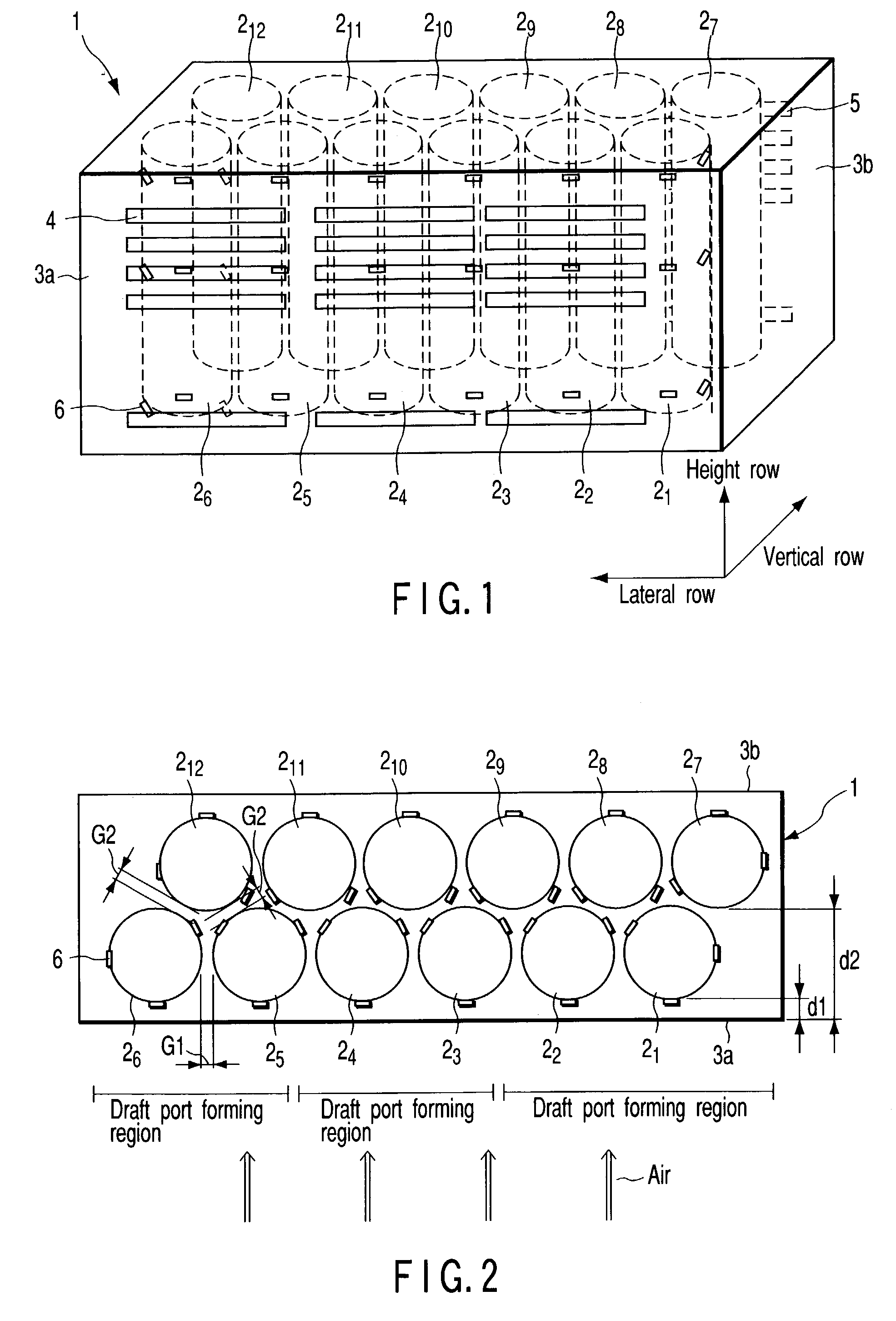
[0154]Twelve cylindrical lithium ion secondary batteries 21 to 212 of 18650 size, 18 mm in diameter, 65 mm in length, and 1.5 Ah in capacity were prepared. Two lithium ion secondary batteries were connected in parallel by resistance welding with Ni tabs to form one unit, and six units were connected in series by leads to form a battery set. The battery array was vertical two rows×lateral six rows. When connecting by tabs, twelve unit cells were mutually spaced. The size of the obtained battery set was 135 mm in width (width in the longitudinal direction), 33 mm in depth (width in the lateral direction), and 65 mm in height.

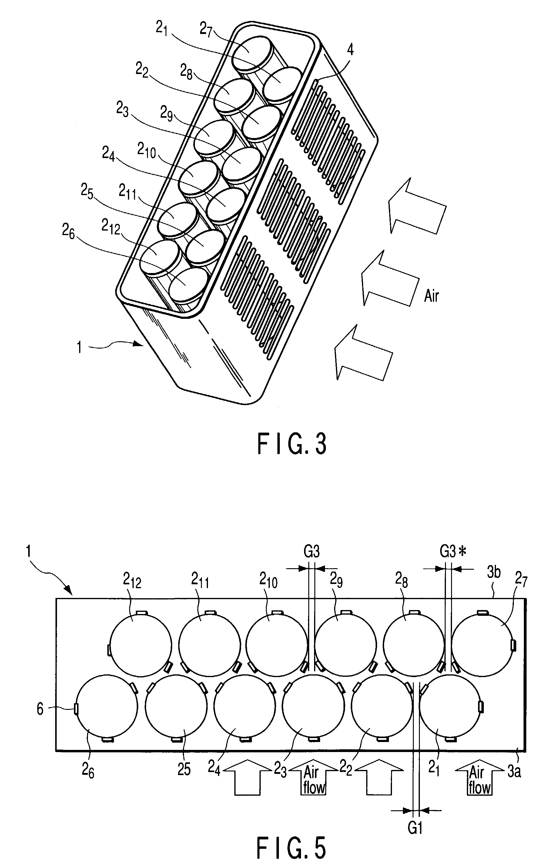
[0155]By forming an outer case 1 by injection molding of epoxy resin around this battery set, the battery set was put in the outer case 1, and a battery pack in the dimensions of 140 mm×70 mm×38 mm having the structure as shown in FIG. 1 and FIG. 2 was fabricated.

[0156]Of the two side walls at the longitudinal direction side of the outer case 1, the first wall 3a ...

examples 2 to 8

[0161]Battery packs were assembled in the same configuration as in Example 1, except that the gap G1 between the unit cells of the vertical first row, or the gap G2 between the unit cells of the vertical first row and the unit cells in the vertical second row was changed as shown in Table 1.

example 9

[0162]A battery pack was assembled in the same configuration as in Example 1, except that a heat equalizing plate was interposed between the unit cells 21 to 26 in the vertical first row and the unit cells 27 to 212 in the vertical second row.

[0163]As the heat equalizing plate, as shown in FIG. 6 and FIG. 7, a corrugated plate shaped along the outer circumference of unit cell was used. The heat equalizing plate was formed of aluminum, measuring 60 mm in height, 119 mm in width, and 1.0 mm in thickness. In the heat equalizing plate, two rectangular lateral slits of 10 mm in height and 25 mm in width were arranged vertically, and three rows were arranged laterally to form ventilation ports.


PUM

PropertyMeasurementUnit
distanceaaaaaaaaaa
heightaaaaaaaaaa
heightaaaaaaaaaa

Abstract

A battery pack includes an outer case, and a plurality of cylindrical lithium ion secondary batteries accommodated in the outer case in vertical N rows and lateral M rows (N rows≦M rows), with a gap between the secondary batteries, wherein the outer case has a draft port opened in a first wall facing an outer circumferential surface of the secondary batteries in the first vertical row, and an exhaust port opened in a second wall positioned at the opposite side of the first wall, in each secondary battery in the first vertical row and the second vertical row, a part of the outer circumferential surface, which is at a shorter distance from the first wall than any other parts, faces the draft port of the outer case.

Description

CROSS-REFERENCE TO RELATED APPLICATIONS[0001]This application is based upon and claims the benefit of priority from the prior Japanese Patent Application No. 2001-401855, filed Dec. 28, 2001, the entire contents of which are incorporated herein by reference.BACKGROUND OF THE INVENTION[0002]1. Field of the Invention[0003]The present invention relates to a battery pack including cylindrical lithium ion secondary batteries, and a rechargeable vacuum cleaner including the battery pack.[0004]2. Description of the Related Art[0005]Lithium ion secondary batteries are small and lightweight, and can be charged and discharged more than 300 cycles repeatedly, and are hence used widely in laptop computers, cellular phones and many other electronic appliances, and the demand is increasing. This is because the weight energy density of the lithium ion secondary battery (LIB) is higher than in the nickel-cadmium secondary battery (Ni—Cd) and nickel mercury secondary battery (Ni-MH). The weight ener...

Claims


Application Information

Patent Timeline
Patent Type & Authority Patents(United States)
IPC IPC(8): H01M2/00H01M2/02H01M2/10H01M2/12H01M6/44H01M10/0525H01M10/36H01M10/50
CPCH01M2/105H01M2/1094H01M6/44H01M10/0525H01M10/5004H01M10/503H01M10/5059H01M10/5063H01M10/5067H01M10/5016Y02E60/122H01M10/613H01M10/625H01M10/643H01M10/6557H01M10/6561H01M10/6563H01M50/213H01M50/24Y02E60/10
Inventor KANAI, HIDEYUKIKANDA, MOTOYAHISANO, KATSUMIIWASAKI, HIDEO
Owner KK TOSHIBA
Why Eureka
Try Eureka