Piezoelectric vibration piece, piezoelectric device using piezoelectric vibration piece, portable phone unit using piezoelectric device, and electronic equipment using piezoelectric device

a piezoelectric and vibration technology, applied in the direction of piezoelectric/electrostrictive device details, piezoelectric/electrostrictive/magnetostrictive devices, piezoelectric/electrostrictive devices, etc., can solve the problems of various harmful effects, achieve better rigidity, prevent distortion, and improve rigidity

Active Publication Date: 2006-03-21
SEIKO EPSON CORP
View PDF6 Cites 29 Cited by
  • Summary
  • Abstract
  • Description
  • Claims
  • Application Information

AI Technical Summary

Benefits of technology

[0018]According to the above structure, the groove provided to each of the vibration arms is a groove with a bottom. Thus, in comparison to the case of forming a penetrated groove to each of the vibration arms, the vibration arms of the present invention will have better rigidity. Further, to each of the grooves is provided a support section (member) formed so as to cross the groove in a width direction to integrally connect the material structuring the vibration arm separated by the groove in the width direction. With such a structure, the support section becomes integrated, especially with the bottom section of the groove, to support the material structuring the vibration arm separated by the groove in the width direction, thereby preventing a distortion from occurring. As a result, better rigidity can be achieved in the twisting direction of the corresponding vibration arm.
[0033]According to an eighth aspect of the invention, to each of the vibration arms of the piezoelectric vibration piece accommodated in this piezoelectric device, a groove with a bottom is formed. The support section provided to the groove is structured to be integrated with the bottom section of the groove, to support the material structuring the vibration arm separated by the groove in the width direction. With such a structure, deformation is prevented from occurring. Thus, rigidity can be achieved in the twisting direction of each of the vibration arms. As such, with respect to the piezoelectric vibration piece accommodated in the piezoelectric device, rigidity is ensured along almost entire length of the vibration arm, with the movement of the vibration arms suppressed in the vertical direction. As such, an appropriate vibration is realized.

Problems solved by technology

Such a vibration property change causes various harmful effects.

Method used


Image

  • Piezoelectric vibration piece, piezoelectric device using piezoelectric vibration piece, portable phone unit using piezoelectric device, and electronic equipment using piezoelectric device
  • Piezoelectric vibration piece, piezoelectric device using piezoelectric vibration piece, portable phone unit using piezoelectric device, and electronic equipment using piezoelectric device
  • Piezoelectric vibration piece, piezoelectric device using piezoelectric vibration piece, portable phone unit using piezoelectric device, and electronic equipment using piezoelectric device

Examples


Embodiment Construction

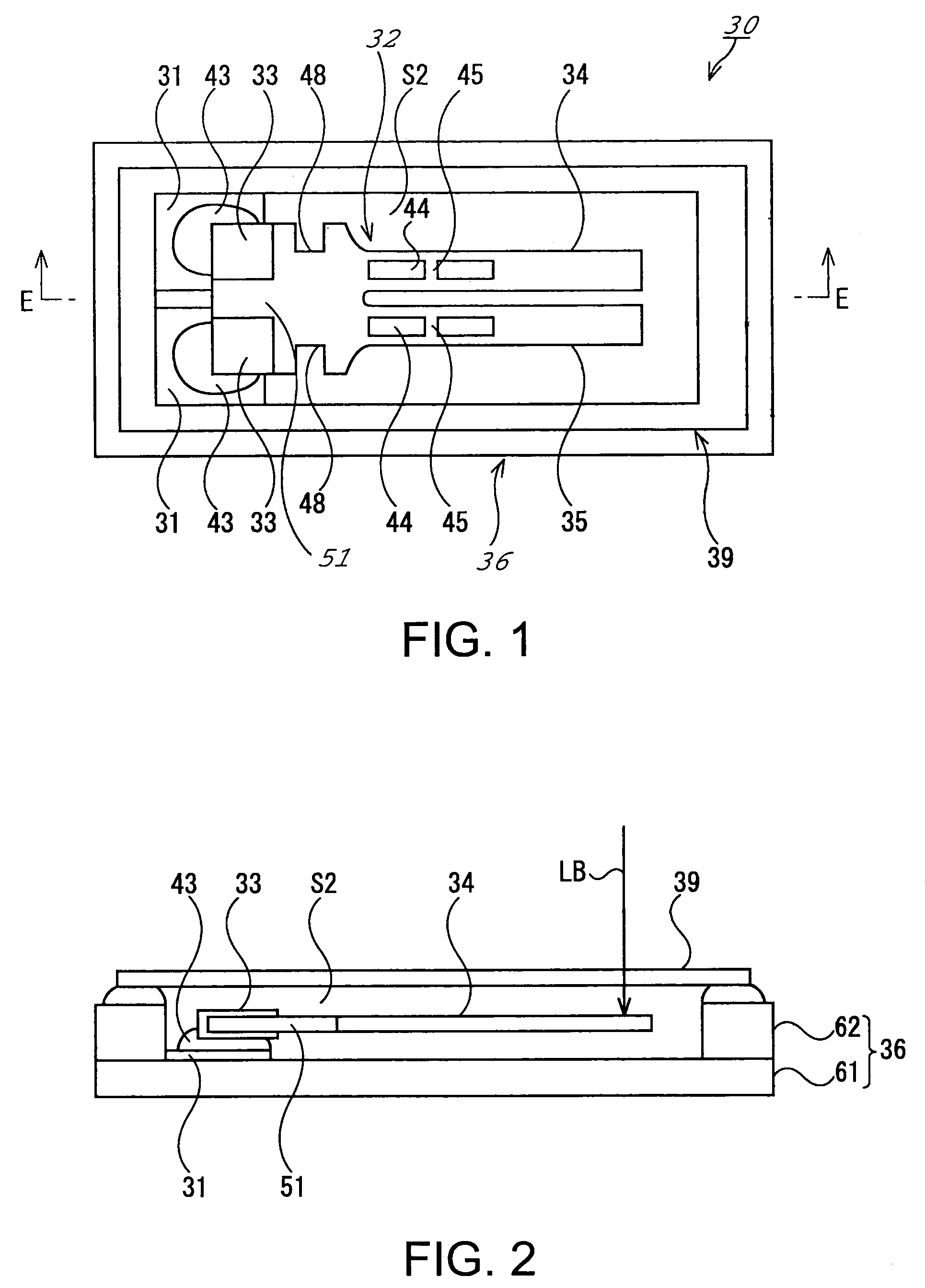
[0051]FIGS. 1 and 2 both show a first embodiment of a piezoelectric device according to the principles the present invention. FIG. 1 is a schematic plan view thereof, and FIG. 2 is a schematic cross-sectional view cut along E—E line of FIG. 1.

[0052]In the drawings, a piezoelectric device 30 is exemplarily structuring a piezoelectric vibrator, and the piezoelectric device 30 is accommodating a piezoelectric vibration piece 32 in its package 36. As an insulating material, the package 36 is formed, for example, by mold-laminating a plurality of substrates. Each of the substrates is a ceramic green sheet made of aluminum oxide, before being subjected to sintering. Inside each of the plurality of substrates is formed a predetermined hole. Thus, after the substrates are laminated, a predetermined inner space S2 is formed inside. In this embodiment, for the purpose of minimizing the thickness of the package 36, a first substrate 61 and a second substrate 62 are laminated together. By elimi...


PUM


Abstract

A piezoelectric vibration piece is provided including a pair of vibration arms that are formed of a piezoelectric material, and extend in a horizontal direction from a base section. Grooves with a bottom are provided in the vibration arms, and extend along the length direction of the corresponding vibration arm. Support sections are provided in such a manner to cross the groove in a width direction to integrally connect the material structuring the vibration arm separated by the groove in the width direction.

Description

FIELD OF THE INVENTION[0001]The present invention relates to a piezoelectric vibration piece, a piezoelectric device accommodating the piezoelectric vibration piece in its package, and a portable phone and electronic equipment using the piezoelectric device.[0002]In small-sized information equipment such as HDDs (Hard Disk Drives), mobile computers, or IC cards, and mobile communications devices such as portable phones, car phones, or paging systems, piezoelectric devices such as piezoelectric vibrators and piezoelectric oscillators each accommodating a piezoelectric vibration piece in their packages are widely used.[0003]FIG. 11 is a schematic cross-sectional view showing an exemplary structure of such a piezoelectric device.[0004]In FIG. 11, a piezoelectric device 1 is accommodating a piezoelectric vibration piece 3 in its package 2. The package 2 is formed in a shape of shallow box made by an insulation material, and the internally-accommodated piezoelectric vibration piece 3 is ...

Claims


Application Information

Patent Timeline
Patent Type & Authority Patents(United States)
IPC IPC(8): H03H9/21H01L41/04H01L41/08H03H9/10H03H9/19H03H9/215
CPCH03H9/21H03H9/1021
Inventor TANAYA, HIDEO
Owner SEIKO EPSON CORP
Why Eureka
Try Eureka