
Decorrelated power amplifier linearizers

a linearizer and power amplifier technology, applied in amplifiers, amplifiers with semiconductor devices/discharge tubes, amplifier modifications to reduce noise influence, etc., can solve the problems of difficult combination, large power efficiency, and high bandwidth of modern wireless systems, and achieve the effect of wide bandwidth and high linearity of radio power amplifiers

Inactive Publication Date: 2006-03-21
COMMSCOPE TECH LLC
View PDF31 Cites 6 Cited by
  • Summary
  • Abstract
  • Description
  • Claims
  • Application Information

AI Technical Summary

Problems solved by technology

Modern wireless systems require both wide bandwidth and high linearity in the radio power amplifiers, a difficult combination to achieve.
For many applications, its drawbacks in power efficiency are more than made up in linearity and bandwidth.
However, it is the difference between the gains that produces the required two nulls, instead of one, in the frequency response; and because the difference between the signals is so small, the difference of CGA gains is unacceptably slow to adapt.
In all other linearizers, however, the linear combinations of branch signals which comprise the uncorrelated modes are not readily determinable in advance.
The presence of unknown observation filters causes two related problems.
First, although adaptation methods based on correlations, such as stochastic gradient, attempt to make changes to CGA gains in directions and amounts that maximally reduce the power in the error signal, the observation filters introduce phase and amplitude shifts.
In the worst case of a 180-degree shift, the adaptation adjustments maximally increase the error signal power—that is, they cause instability and divergence.
The second problem is that it is difficult to transform the branch signals to uncorrelated modes if their monitored counterparts do not have a known relationship to them.

Method used


Image

  • Decorrelated power amplifier linearizers
  • Decorrelated power amplifier linearizers
  • Decorrelated power amplifier linearizers

Examples


Embodiment Construction

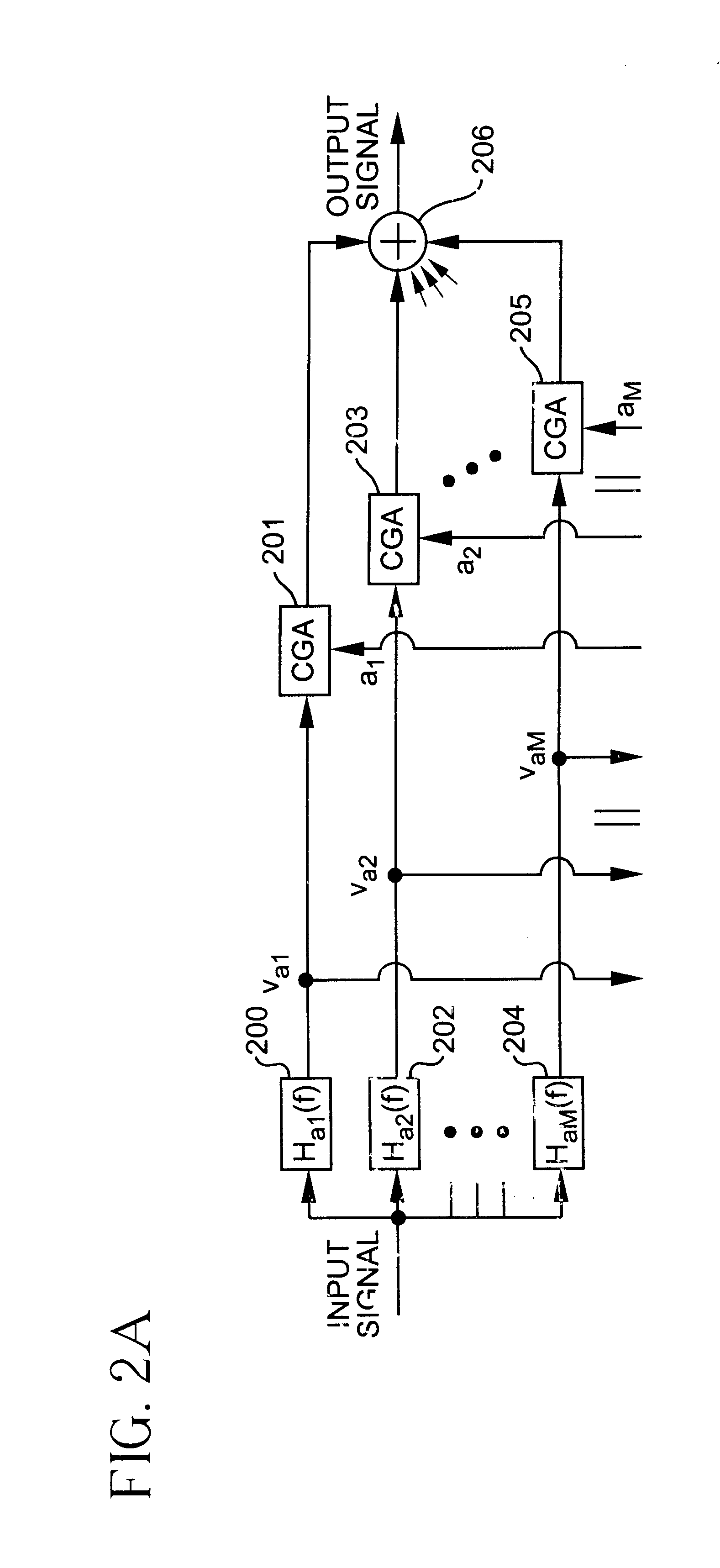
[0033]The present invention includes procedures by which the branch signals νa1 to νaM of a multibranch signal adjuster may be decorrelated for any number of branches. These procedures apply to signal adjuster in which the branch signals have equal or unequal power. Decorrelating the branch signals in the adaptation process provides faster convergence than not decorrelating. The present invention also includes procedures for both self-calibrating and decorrelating an uncalibrated signal adjuster.

[0034]Accordingly, there are two classes of linearizers. In the first linearizer class, calibration is unnecessary or has already been achieved, and thus only decorrelation is performed. In the second linearizer class, calibration is desired, and thus self-calibration and decorrelation are performed integrally. These two linearizer classes will be addressed in that order.

[0035]First Linearizer Class

[0036]If calibration is unnecessary, or has already been achieved, there are no calibration er...


PUM


Abstract

Procedures for decorrelating the branch signals of a signal adjuster of an amplifier linearizer are presented herein. The decorrelation procedures can be performed with or without self-calibration.

Description

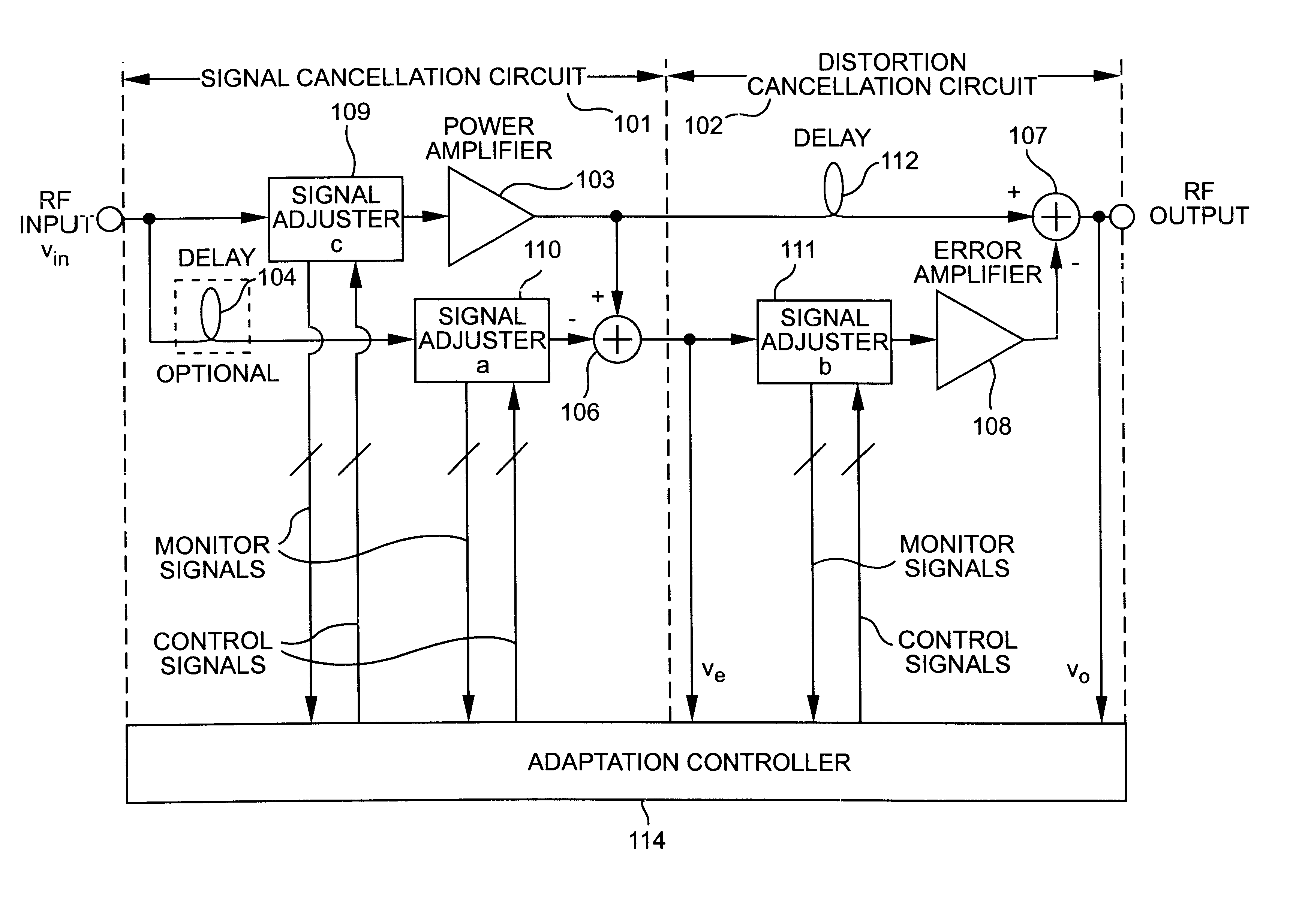
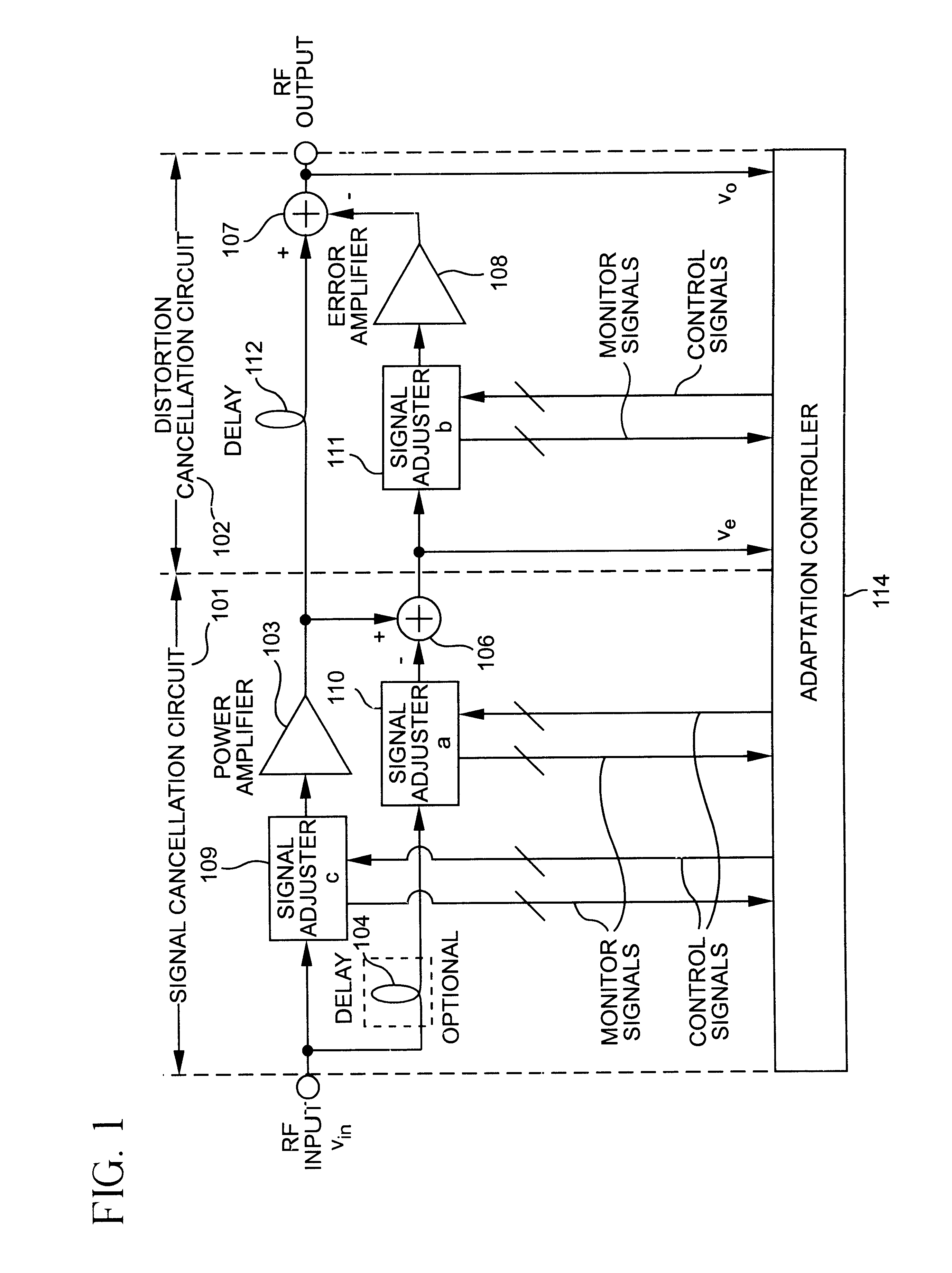
CROSS-REFERENCE TO RELATED APPLICATIONS[0001]This application claims priority to U.S. patent application Ser. No. 60 / 301,978 filed Jun. 28, 2001.FIELD OF THE INVENTION[0002]This application generally pertains to, but is not limited to, linearizers used in power amplifiers, for example, RF power amplifiers used in wireless communication systems.BACKGROUND OF THE INVENTION[0003]Modern wireless systems require both wide bandwidth and high linearity in the radio power amplifiers, a difficult combination to achieve. To date, the most successful architecture to correct for the nonlinearity in the power amplifier has been feedforward linearization. For many applications, its drawbacks in power efficiency are more than made up in linearity and bandwidth.[0004]A generic feedforward linearizer for a power amplifier is shown in FIG. 1. The relationship of the output to the input of the circuits labeled “signal adjuster” (109, 110, 111) depends on the settings of one or more control parameters ...

Claims


Application Information

Patent Timeline
IPC IPC(8): H03F1/26H03F1/30H03F1/32
CPCH03F1/3247H03F1/3229
Inventor CAVERS, JAMES K.JOHNSON, THOMAS
Owner COMMSCOPE TECH LLC
Learn More