
Constant angular velocity disk label printing

a constant angular velocity, disk label technology, applied in the direction of digital signal error detection/correction, instruments, recording signal processing, etc., can solve the problem of often damaged recording layer, and achieve the effect of improving adhesion and controlling thermal conductivity

Inactive Publication Date: 2006-03-21
YAMAHA CORP
View PDF113 Cites 42 Cited by
  • Summary
  • Abstract
  • Description
  • Claims
  • Application Information

AI Technical Summary

Benefits of technology

Enables the direct and efficient formation of images on optical disk labels without damaging the recording layer, using the optical disk unit's laser beam to modify the visible light characteristics, thus providing a reliable and equipment-free solution for labeling.

Problems solved by technology

According to the method in which contents are written directly on the label surface of the disk, a recording layer is often damaged by a strong writing action effected by use of a stiff pencil.

Method used


Image

  • Constant angular velocity disk label printing
  • Constant angular velocity disk label printing
  • Constant angular velocity disk label printing

Examples


Embodiment Construction

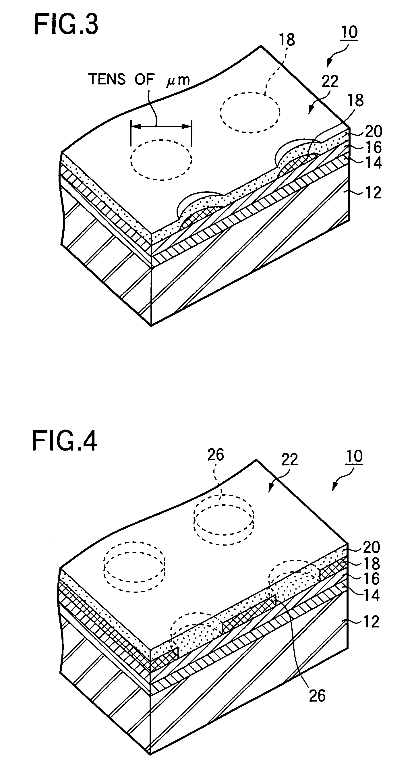
[0031]Embodiments of the present invention will be described hereinafter. FIG. 1 is a partial cross section (the thickness of each layer differs from that of an actual layer, and a guide groove is omitted from the drawing) showing an optical disk according to the embodiment of present invention. The embodiment shows an example in which the present invention is applied to a CD-R disk. As to optical disk 10, a pigment layer (i.e., a recording layer) 14, a reflection layer 16, a visible light characteristic changing layer 18 and a protective layer 20 are sequentially formed on a single side of a transparent substrate so as to constitute the optical disk 10. The optical disk 10 is identical with an ordinary CD-R disk, except for provision of the visible light characteristic changing layer 18. The visible light characteristic changing layer 18 can be seen through a transparent protective layer 20 from a label surface 22. The reflectivity, permeability, or optical-scattering characteristi...


PUM

PropertyMeasurementUnit
wavelengthaaaaaaaaaa
poweraaaaaaaaaa
thicknessaaaaaaaaaa

Abstract

A visible light characteristic changing layer is formed in a location which can be viewed from a part of a label surface of an optical medium. The optical medium is set on a turntable of an optical disk unit, which may be rotated at a constant angular velocity, while the power of a laser beam is modulated in accordance with image data. The optical pickup operates at a first power level when changing a visible light characteristic of the optical medium to form the visible information and the optical pickup operates at a lower power level when not changing a visible light characteristic of the optical medium. As a result, a visible-light reflectivity of the visible light characteristic layer is changed, thereby forming an image corresponding to the image data on the label surface, A tracking servo operation is turned off while the optical pickup forms the visible information.

Description

CROSS REFERENCE TO RELATED APPLICATION[0001]This application is a continuation of application Ser. No. 10 / 053,238, filed Oct. 29, 2001, the entire disclosure of which is herein expressly incorporated by reference.BACKGROUND OF THE INVENTION[0002]The present invention relates to a method of printing a label provided on an optical disk, to an optical disk unit, and relates to an optical disk in which a label can be subjected to printing by utilization of a laser beam output from an optical disk unit.[0003]In a recordable optical disk, information about contents recorded thereon (e.g., titles) is described on an optical disk by a user so that the recorded contents can be checked visually. In the case of a single-sided optical disk which is handled as a single disk without being housed in a cartridge, such as a CD-system optical disk i.e., a CD-R (CD recordable), a CD-RW (CD rewritable),etc. the information is usually written directly on a label surface of the optical disk with a pen. A...

Claims


Application Information

Patent Timeline
Patent Type & Authority Patents(United States)
IPC IPC(8): B41J2/47B41J3/407G11B5/09G11B7/0037G11B7/0045G11B7/085G11B7/2403G11B7/24094G11B7/26G11B23/40
CPCB41J2/47B41J3/4071B41J19/16G11B23/40G11B7/2403G11B7/24094G11B7/0037G11B7/08505
Inventor HONDA, KAZUHIKOKONDO, TAMON
Owner YAMAHA CORP
Learn More