Three-dimensional display system

a display system and three-dimensional technology, applied in optics, instruments, electrical equipment, etc., can solve the problems of dramatic decrease in efforts to develop other forms of 3-d, no satisfactory method for producing affordable 3-d imaging of acceptable quality, and no satisfactory method in the prior art for delivering 3-d images over conventional bandwidths. , to achieve the effect of less bandwidth, low cost and convenient us

Inactive Publication Date: 2006-03-21
DOLGOFF EUGENE
View PDF19 Cites 220 Cited by
  • Summary
  • Abstract
  • Description
  • Claims
  • Application Information

AI Technical Summary

Benefits of technology

[0022]The invention disclosed herein provides a 3-D display system based on the inventor's realization that an observor (interchangeably referred to herein as a viewer or player) experiences a perception of 3-D as seen in real life when presented with as few as two planar images at different depths. An advantage is that the many of the embodiments disclosed herein present such images at low cost and in a manner that is remarkably easy to use. Moreover video images in accordance with the present invention can be transmitted using significantly less bandwidth than convention 3-D imaging techniques.

Problems solved by technology

The prior art discloses no satisfactory methodology that produces affordable 3-D imaging of an acceptable quality.
Additionally no method has been devised for transmission of 3-D images over conventional bandwidths.
According to Okoshi, the popularity of Cinerama resulted in a dramatic decrease in efforts to develop other forms of 3-D.
Conventional 3-D stereo techniques lack an ability to convey parallax, but although parallax is not absolutely essential for a viewer to experience 3-D, its presence adds a great deal of realism to 3-D imaging.
Lack of the depth disparity phenomenon leads to eye strain and headaches after extended periods of viewing in current 3-D imaging systems, because of the conflict between accommodation and convergence.
Second, the objects depicted on screen were often small compared to the huge screen size.
This caused the brain to lose depth perception with regard to that object and just see it as a curved flat object.
Due to our eyes' limited depth of field, we can never get all objects (or even all parts of any single three-dimensional object) into best focus at any one time.
In such an experience, fatigue, eyestrain, and headaches result since the objects are, at least in part, not really in focus in the same plane as convergence makes them appear.
Also, the further out of the plane of best focus the image appears due to convergence, the harder it is for the viewer to see a 3-D image instead of a double image.
However, two different images viewed from two different angles cannot line up exactly.

Method used


Image

  • Three-dimensional display system
  • Three-dimensional display system
  • Three-dimensional display system

Examples


Embodiment Construction

[0188]Real-Depth 3-D Imaging

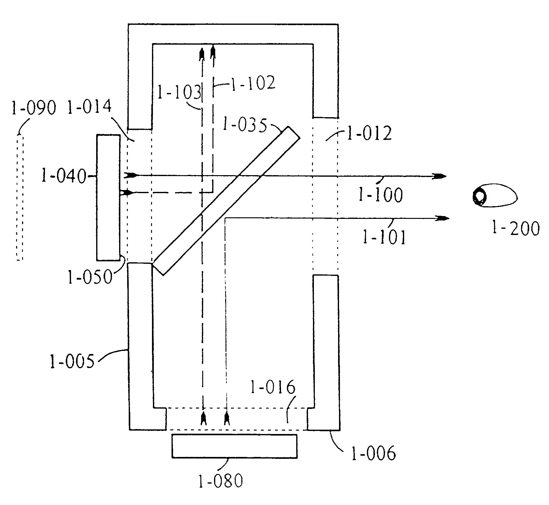
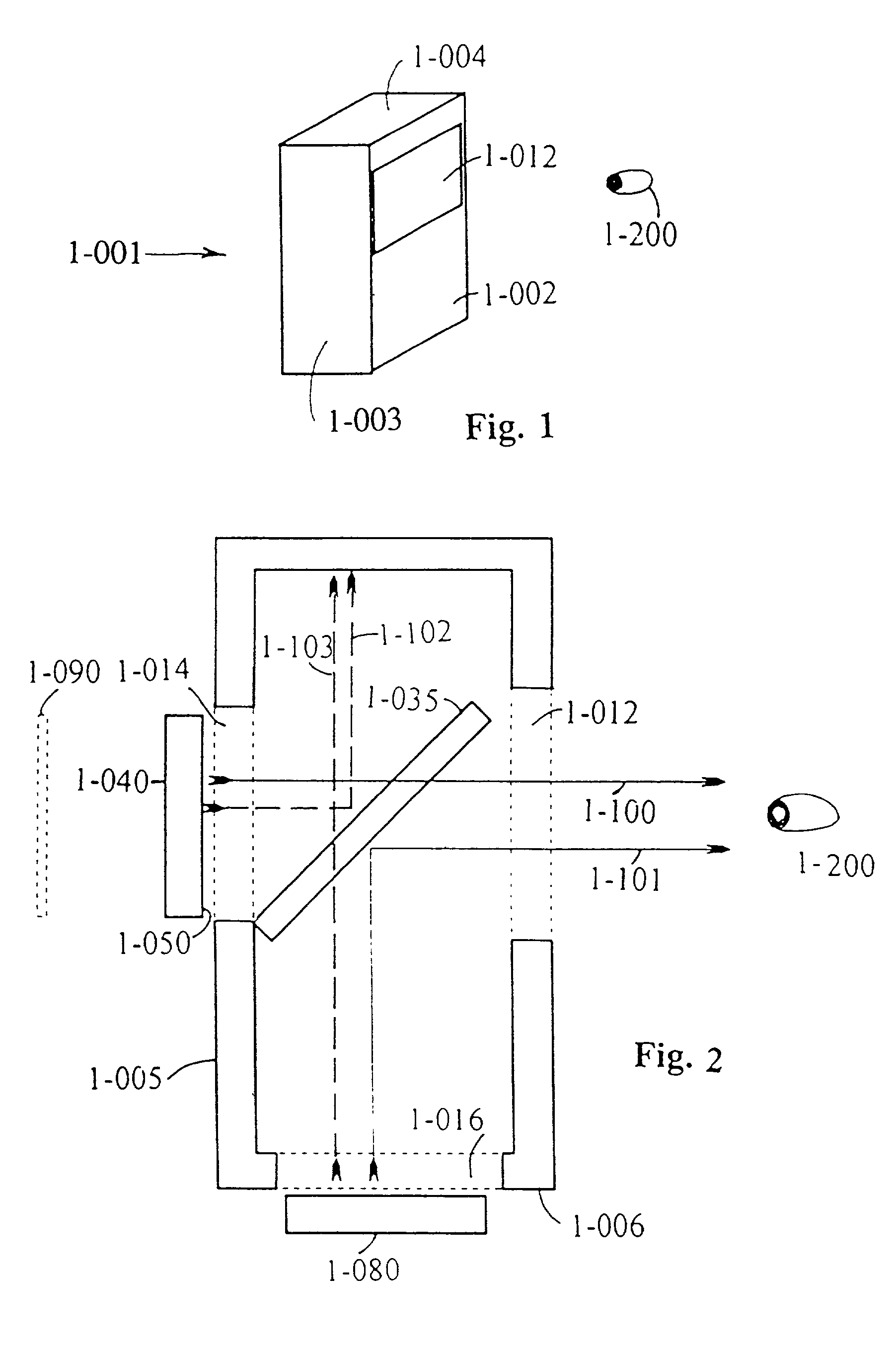
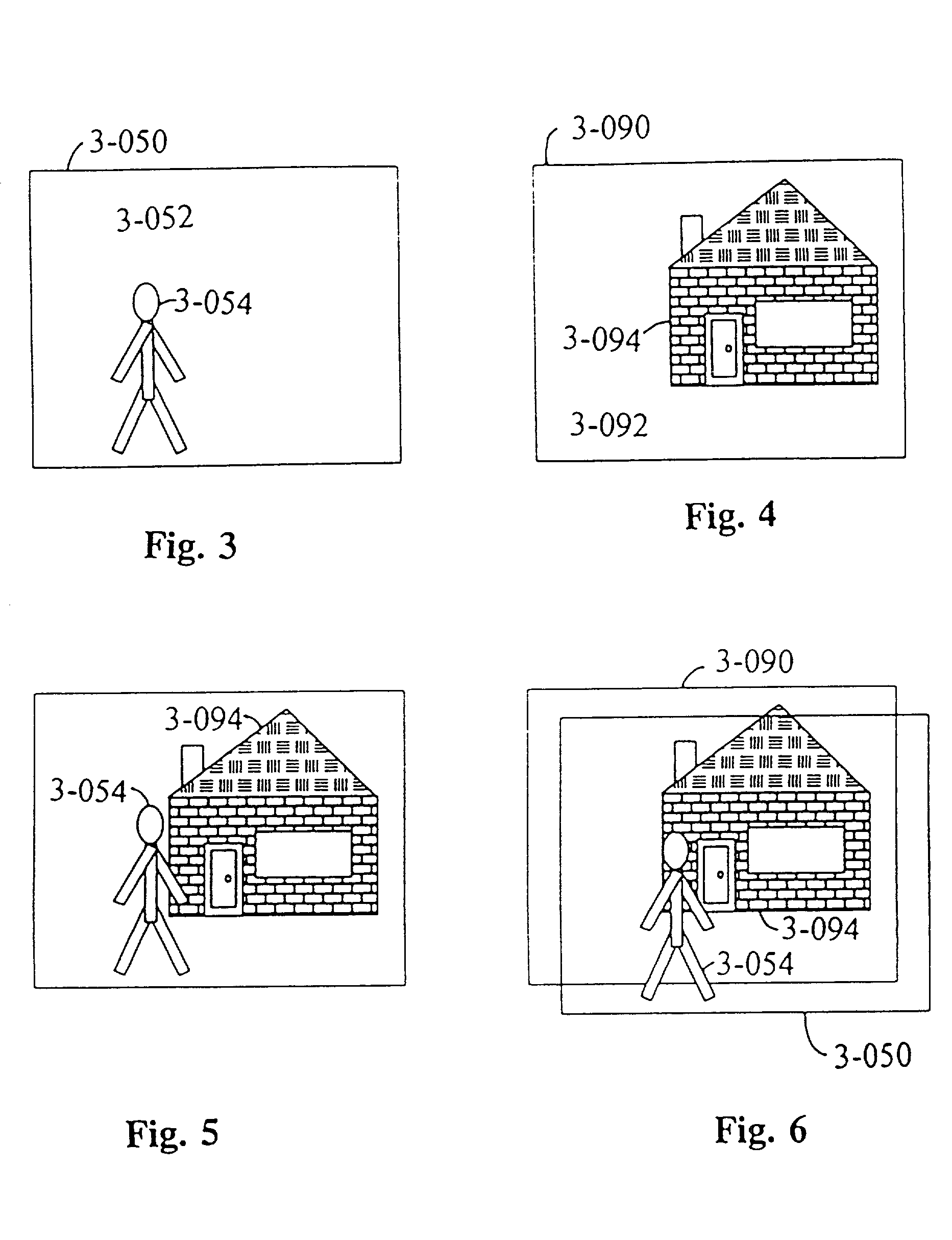
[0189]The present invention provides what may be termed real-depth imaging, since there are real differences in depth between images of objects in a scene. In accordance with the invention, different objects at different depths in a scene are presented in different planes in space, one behind the other. The object areas of each plane are perceived as opaque, and the non-object areas are clear to allow observation of the images in more distant planes.

[0190]The inventor's experimentation revealed that images created in only two planes provide a satisfactory real-depth experience. The inventor's discovery that only two images, projected in different planes, are needed to achieve a 3-D experience greatly simplifies from those of the prior art, the system necessary to produce such images. Moreover, the information content (i.e. the bandwidth) necessary to transmit such images is at a level which can be readily transmitted via a conventional TV channel or over ...


PUM


Abstract

An image display system provides a viewer with an experience of three dimensional images by presenting a composite image source. The system includes first and second image sources, a beamcombiner, a lens and a reflective element. The reflective elements reflects the image of the second image source to the beamcombiner. The first and second image sources, the beamcombiner, and the single lens present a foreground image and a background image, with the background image presented at a greater distance from the viewer than the foreground image. The viewer perceives the foreground image and the background image as part of a scene having depth.

Description

CROSS REFERENCE TO RELATED APPLICATION[0001]This application is a continuation of U.S. patent application 08 / 774,569, filed Dec. 31, 1996, now U.S. Pat. No. 6,310,733, which claims priority under 35 U.S.C. Section 119(e) from U.S. Provisional Patent Application 60 / 233,677, filed Aug. 16, 1996. The entire contents of the aforementioned two patent applications are hereby incorporated herein by reference.BACKGROUND OF THE INVENTION[0002]The present invention relates to image display systems, including technology for the creation of aerial real images and other three-dimensional (3-D) effects. More particularly, the present invention involves improved imaging systems, especially useful for computer displays and videoconferencing. More particularly, the present invention involves improved imaging systems, capable of providing multiplane images from video or other sources that simulate the perception of 3-D real depth. The present invention also has the capacity to provide, simultaneously...

Claims


Application Information

Patent Timeline
Patent Type & Authority Patents(United States)
IPC IPC(8): G02B27/14G02B27/22G02BG09G3/00H04N13/00
CPCG02B27/2278G09G3/001H04N13/0495H04N13/0443G09G3/003H04N13/395H04N13/346G02B30/52
Inventor DOLGOFF, EUGENE
Owner DOLGOFF EUGENE
Why Eureka
Try Eureka