Method and apparatus for reducing co-channel interference in a communication system

a communication system and cochannel interference technology, applied in the field of communication systems, can solve the problems of affecting the performance of communication systems, affecting the efficiency of communication systems, and often encountered by users within communication systems, and achieve significant increases in the level of cochannel interferen

Inactive Publication Date: 2006-03-21
GOOGLE TECH HLDG LLC
View PDF8 Cites 192 Cited by
  • Summary
  • Abstract
  • Description
  • Claims
  • Application Information

AI Technical Summary

Problems solved by technology

Interference often hinders performance of communication systems.
One type of interference often encountered by a user within a communication system is interference generated by the transmissions of other users.
This is typically caused by many users transmitting within the same channel (e.g., frequency band, time slot, or spreading code), and referred to as co-channel interference.
However, given the price of spectrum, future communications systems will be characterized by aggressive reuse patterns that will result in significantly increased levels of co-channel interference.
Signal spreading methods (such as direct sequence spread spectrum) can be used to provide processing gain over co-channel interference, but this limits the data rate that can be supported.
Moreover, dynamic channel allocation methods have been proposed, but these methods are difficult to implement because they require monitoring of the channel quality, the channel availability, and they also require communication links to be established between different base stations so that the channel allocation process can be controlled and monitored.
Moreover, as cellular systems evolve from circuit-centric operation to packet-centric operation, the channel utilization pattern in any given cell becomes much more dynamic, leading to further implementation difficulties (e.g., the channel utilization may change more quickly than the response time of the channel allocation process, making it essentially ineffective).

Method used


Image

  • Method and apparatus for reducing co-channel interference in a communication system
  • Method and apparatus for reducing co-channel interference in a communication system
  • Method and apparatus for reducing co-channel interference in a communication system

Examples


Embodiment Construction

[0048]The above text described how the proposed interference avoidance method can be applied to a transmitted frame in total, or to a subset of a frame such as a control channel or data channel. In this section, additional examples are provided to clarify some of the ways for performing interference avoidance on multiple channels in a frame in accordance with the preferred embodiment of the present invention. These examples are for illustration purposes and are not meant to limit the scope of the present invention to any particular example described below.

[0049]The first example performs interference avoidance independently on two channels of a frame, namely a control channel and a data channel, but does not use the interference avoidance method on other channels in the frame. This is illustrated in FIG. 8. In this example, the control channel, data channel, and other channels have separate locations within the frame. As a result, a control channel in one sector will never interfere...


PUM


Abstract

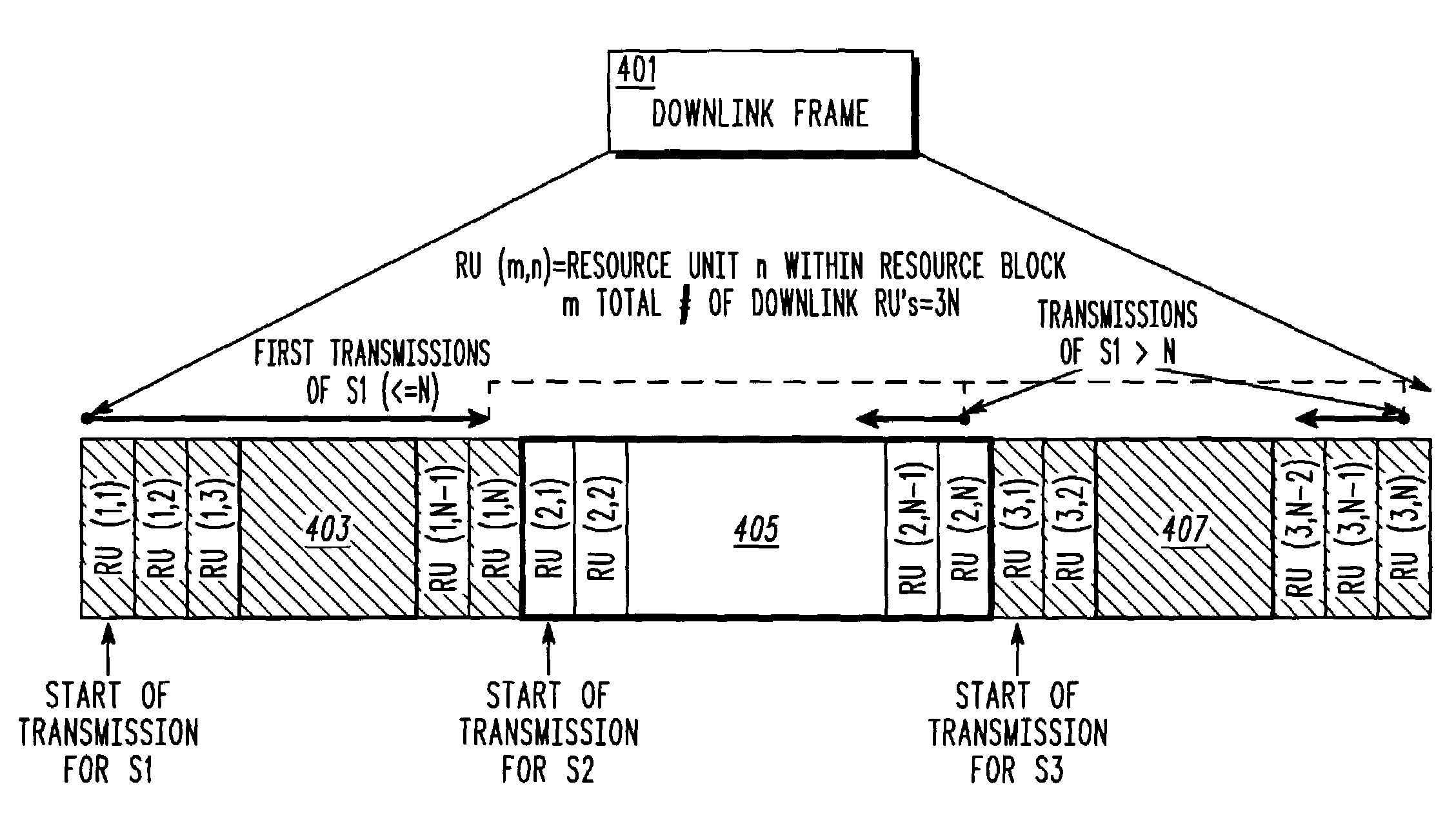
A downlink frame (401) is divided in to similar sized resource blocks (403, 405, 407) with each co-channel sector scheduled to transmit from the beginning of its respective assigned resource block. Transmissions to remote units within the particular sector will occur only within the particular resource block, up to a point where all N resource units have been utilized. Beyond that point, additional transmissions are scheduled to be transmitted at the end of the resource blocks assigned to the other sectors.

Description

FIELD OF THE INVENTION[0001]The present invention relates generally to communication systems and in particular, to a method and apparatus for reducing co-channel interference within such communication systems.BACKGROUND OF THE INVENTION[0002]Interference often hinders performance of communication systems. One type of interference often encountered by a user within a communication system is interference generated by the transmissions of other users. This is typically caused by many users transmitting within the same channel (e.g., frequency band, time slot, or spreading code), and referred to as co-channel interference. In order to reduce co-channel interference many communication systems employ a channel reuse pattern, where adjacent transmitters transmit on different channels. However, given the price of spectrum, future communications systems will be characterized by aggressive reuse patterns that will result in significantly increased levels of co-channel interference.[0003]Vario...

Claims


Application Information

Patent Timeline
Patent Type & Authority Patents(United States)
IPC IPC(8): H04Q7/36H04L12/56H04W16/10H04W72/12
CPCH04W72/082H04L5/0037H04L5/0044H04W72/1257H04L5/023H04L5/005H04W72/541H04W72/535H04B7/2612
Inventor BAUM, KEVIN L.CLASSON, BRIAN K.CUDAK, MARK C.NANGIA, VIJAY
Owner GOOGLE TECH HLDG LLC
Why Eureka
Try Eureka