Pattern identification apparatus, pattern identification method, and pattern identification program

a pattern identification and pattern identification technology, applied in image analysis, instruments, computing, etc., can solve the problems of low pattern recognition accuracy, and difficulty in high-speed processing, and achieve high-speed pattern identification without reducing the accuracy of collation.

Inactive Publication Date: 2006-03-21
FUJITSU LTD
View PDF13 Cites 2 Cited by
  • Summary
  • Abstract
  • Description
  • Claims
  • Application Information

AI Technical Summary

Benefits of technology

[0008]The present invention has been made in view of the circumstances as referred to above, and has for its object to provide a pattern identification apparatus, a pattern identification method, and a pattern identification program which are capable of performing collation at a high speed without reducing the accuracy of collation in pattern identification by adopting a feedback-type collation method in which collation is first carried out with a search area added by margins to provide a size wider than that of a registered image, and then collation is again performed by deleting the margins based on the result of the first collation.
[0010]Based on the result of comparison and collation obtained by the first collation section, the second collation section again performs comparison and collation using an image cut out in a size smaller than the size of the image used in the first collation section. Thus, even when a characteristic portion of the image is used for identification for example, noise (garbage) included in margins of the image can be removed, whereby it is possible to perform collation at a high speed and with high accuracy and improve reliability in operation as well. In an embodiment of the present invention, the storage section is constituted by a layout data base (DB), and the first and second collation sections, the cutting section and the identification section are constituted by a collation section and a control section.
[0012]With such an arrangement, as the result of the collation (first collation) carried out by the first collation section, there are provided minimum points at which the difference level becomes a local minimum for instance, and the second collation section again performs collation using the local minimum points whereby the margins can be deleted accurately from the image used in the first collation. Accordingly, the second collation section can perform second collation with an extremely high degree of accuracy.
[0014]In this manner, the first collation section performs comparison and collation using an image cut out in a size wider than the registered pattern, and based on the result of comparison thus obtained by the first collation section, the second collation section again performs comparison and collation using an image cut out in a size smaller than that of the image used in the first collation section. Thus, problems such as displacements of coordinates occurring when an image, which is an object to be identified, is read in, are obviated, thereby improving the accuracy in the image collation. As a result, misidentification can be reduced to a substantial extent. In an embodiment of the present invention, the storage section is constituted by a layout data base (DB) as in the above case, and the first and second collation sections, the first and second cutting sections and the identification section are constituted by a collation section and a control section.
[0016]With this method, it is possible to improve the accuracy in collation in the case of documents being identified, thus reducing misidentification of the documents to a considerable extent.
[0017]Moreover, the present invention provides a pattern identification program for making a computer execute the above-mentioned pattern identification method. If such a program is stored in the computer, the collation accuracy can be improved in the processing of identifying documents, slits and so on.

Problems solved by technology

However, this search processing deals with a large mount of data and the number of search operations is also great, thus making it difficult to perform the processing at a high speed.
However, conspicuity or remarkableness of the characteristic portion of the registered image is weakened by these margins so that accuracy in the pattern recognition might be reduced, causing errors in the collation result.
As a consequence, there arises a problem that reliability in the collation result is reduced.

Method used


Image

  • Pattern identification apparatus, pattern identification method, and pattern identification program
  • Pattern identification apparatus, pattern identification method, and pattern identification program
  • Pattern identification apparatus, pattern identification method, and pattern identification program

Examples


Embodiment Construction

[0035]Now, a preferred embodiment of the present invention will be described in detail while referring to the accompanying drawings.

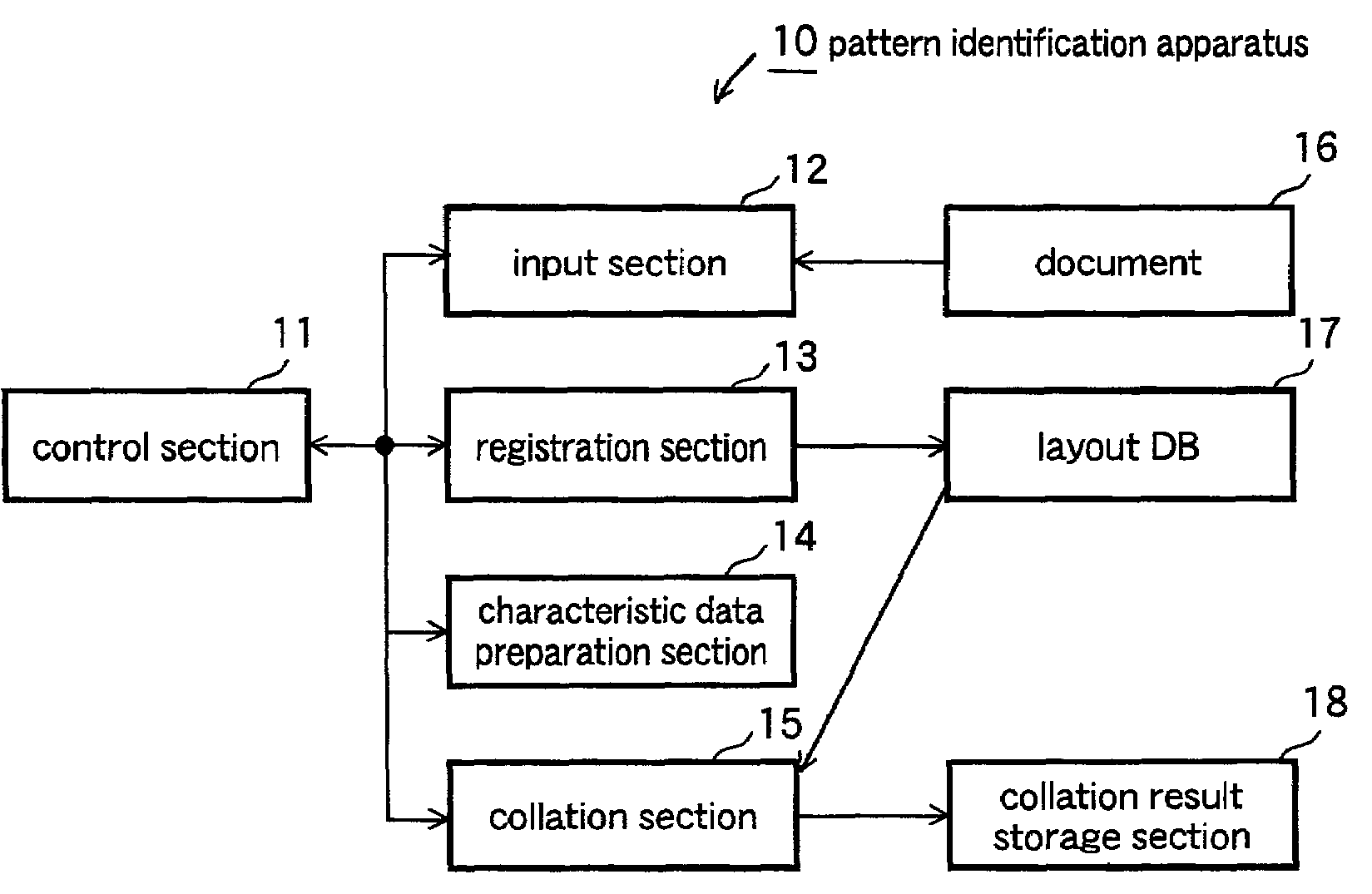
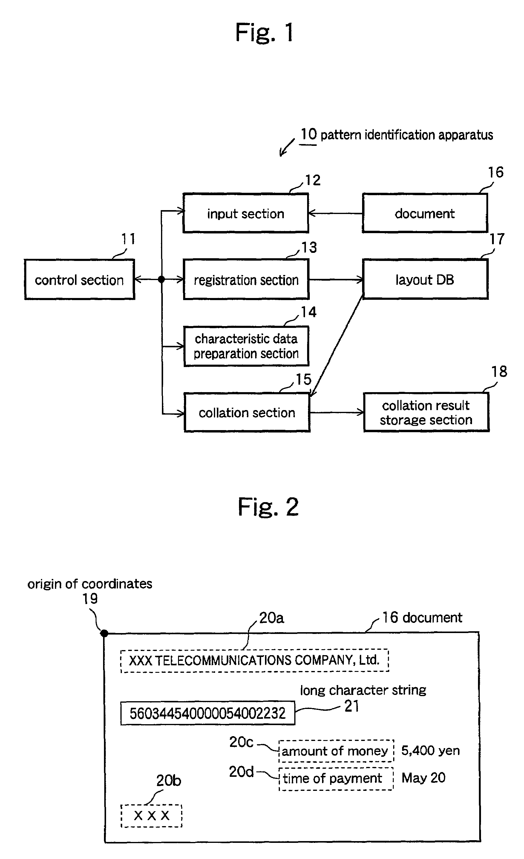
[0036]FIG. 1 is a block diagram schematically illustrating the basic construction of a pattern identification apparatus according to an embodiment of the present invention. As shown in this figure, a pattern identification apparatus, generally designated at reference numeral 10, includes an input section 12 for reading characters, images and the like printed on a variety of slits or documents 16, a registration section 13 for registering a variety of pieces of information on the documents input by the input section 12 into a layout data base (DB) 17, a characteristic data preparation section 14 for preparing characteristic data to be described later in detail from the images on the document input to the input section 12, a collation section 15 for performing comparison and collation between a registered image in the layout DB 17 and a search image as an...


PUM


Abstract

Collation can be carried out at a high speed without reducing the accuracy thereof, whereby processing of identifying documents is accurately performed at a high speed. To this end, characteristic data of a predetermined pattern is registered in advance. Characteristic data in a first area greater than an area of the predetermined pattern registered in advance in an image to be identified is compared and collated with characteristic data of the predetermined pattern. A second area smaller than the first area is cut out from the first area based on the result of comparison, so that characteristic data of an image in the second area is compared and collated with the characteristic data of the predetermined pattern, thus making it possible to identify the predetermined pattern contained in the image based on the result of comparison.

Description

BACKGROUND OF THE INVENTION[0001]1. Field of the Invention[0002]The present invention relates to a pattern identification apparatus, a pattern identification method, and a the pattern identification program in which a predetermined image is compared and collated with a predetermined pattern such as an image stored in advance to identify a predetermined pattern contained in the predetermined image. More specifically, the present invention relates to a pattern identification apparatus, a pattern identification method, and a pattern identification program capable of identifying documents, slits and the like by comparing and collating images of a variety of kinds of them with specific registered images.[0003]2. Description of the Related Art[0004]The payments or transfers of electricity bills, gas bills, municipal taxes (taxes, public funds), etc., are processed by using the data (the amounts of money for payments, the times for payments, etc.) described in a variety of tax documents, p...

Claims


Application Information

Patent Timeline
Patent Type & Authority Patents(United States)
IPC IPC(8): G06K9/00G06V30/184G06T7/00G06V30/10
CPCG06K9/50G06V30/10G06V30/184
Inventor WAIDA, TOSHIYUKIEGUCHI, SHINICHIKANAMOTO, KOUICHIYABUKI, MAKICHIBA, KOICHIKOBARA, KATSUTOSHISATO, OSAMUYAMAMOTO, KAZUNORIKATSUMATA, YUTAKA
Owner FUJITSU LTD
Why Eureka
Try Eureka