
Dust removal apparatus

a technology of dust removal apparatus and dust removal surface, which is applied in the direction of cleaning equipment, brushes, coatings, etc., can solve the problems of increasing the cost unsatisfactory painting defects, and reducing the service life of the removal apparatus, so as to prevent undesired scattering of dust particles, effectively block the wind produced by the rotation, and efficiently remove the workpiece surface

Inactive Publication Date: 2006-03-28
HONDA MOTOR CO LTD
View PDF9 Cites 12 Cited by
  • Summary
  • Abstract
  • Description
  • Claims
  • Application Information

AI Technical Summary

Benefits of technology

[0014]In view of the foregoing prior art problems, it is an object of the present invention to provide an improved dust removal apparatus which can efficiently remove dust particles from the surface of a workpiece using simple construction.
[0016]In a specific embodiment, the rear air nozzle unit is secured to a rear end portion of the hood, and the front air nozzle unit is secured to a front end portion of the hood. The front air nozzle unit can form an air curtain in front of the rotary brush by emitting air jets onto the workpiece surface. The thus-formed air curtain can effectively prevent dust particles from scattering forward to the outside of the rotary brush. Therefore, there is no need to provide an extra rotary brush right in front of the hood as in the conventional dust removal apparatus. In addition, by the front air nozzle unit thus emitting air jets onto the region of the workpiece surface near the rotary brush along the linear front end edge of the hood, it is possible to effectively cause dust particles, adhering to the workpiece surface, to get detached from or more or less floated off the workpiece surface. This way, the dust particles can be wiped away by the rotary brush with a significantly increased efficiency.
[0017]Preferably, the exhaust duct is connected to the hood via a tapering connection member having an opening of a larger sectional area at one end thereof adjacent to the hood and having an opening of a smaller sectional area at the other end thereof adjacent to the exhaust duct or opposite the hood. The tapering connection member is interposed between the exhaust duct and the hood, and the sectional area of the opening at the one end of the tapering connection member adjacent to the hood is greater than that at the other end adjacent to the exhaust duct. The one end of the tapering connection member, having an opening of the larger sectional area, opens to a predetermined dust removing space defined by the semi-cylindrical hood, so that dust particles floating within the hood (i.e., dust removing space) can be efficiently guided to the exhaust duct.
[0019]In a specific embodiment of the invention, the rear air nozzle unit emits the air jets in a direction inclined rearwardly, relative to the vertical, at an inclination angle in a range of 20–25°. When the inclination angle of the air jet emission by the rear air nozzle unit is below 20°, the inclination angle is too small, so that the air jet emission by the rear air nozzle unit can not appropriately block a wind produced by the rotation of the rotary brush. Therefore, due to the wind produced by the rotation of the rotary brush, dust particles detached from or floated off the workpiece surface may undesirably scatter, through the air jets emitted by the rear air nozzle unit, to the outside of the rotary brush, which would prevent efficient removal of the dust particles from the workpiece surface. Thus, in the present invention, the inclination angle of the air jet emission by the rear air nozzle unit is set to 20° or over, in order to effectively block the wind produced by the rotation of the rotary brush and thereby prevent undesired scattering of dust particles so that dust particles can be efficiently removed from the workpiece surface.
[0020]When, on the other hand, the inclination angle of the air jet emission by the rear air nozzle unit is over 25°, the inclination angle is too great, so that the air jets emitted by the rear air nozzle unit go deep into (toward a rotation shaft or hub of) the rotary brush and thus prevent dust particles, detached from or floated off the workpiece surface, from being directed toward and introduced into the exhaust duct. Therefore, in the present invention, the inclination angle of the air jet emission by the rear air nozzle unit is set to 25° or below, in order to effectively prevent the air jets, emitted by the rear air nozzle unit, from going deep into the rotary brush, so that dust particles can be efficiently directed to the exhaust duct by the air jets emitted by the rear air nozzle unit.

Problems solved by technology

In painting a body surface of a motor vehicle, undesired painting defects may result unless dust particles present on the body surface are cleared prior to the painting.
The provision of these two brushes 101 and 104 and two drives therefor would considerably complicate the construction of the dust removal apparatus 100 and increase the cost of the removal apparatus 100.
However, with the illustrated construction of FIG. 14, it is difficult for the suction force to sufficiently act on spaces 108 between the exhaust ducts 103, so that dust particles 107 trapped in these spaces 108 can not be discharged through the exhaust ducts 103.

Method used


Image

  • Dust removal apparatus
  • Dust removal apparatus
  • Dust removal apparatus

Examples


Embodiment Construction

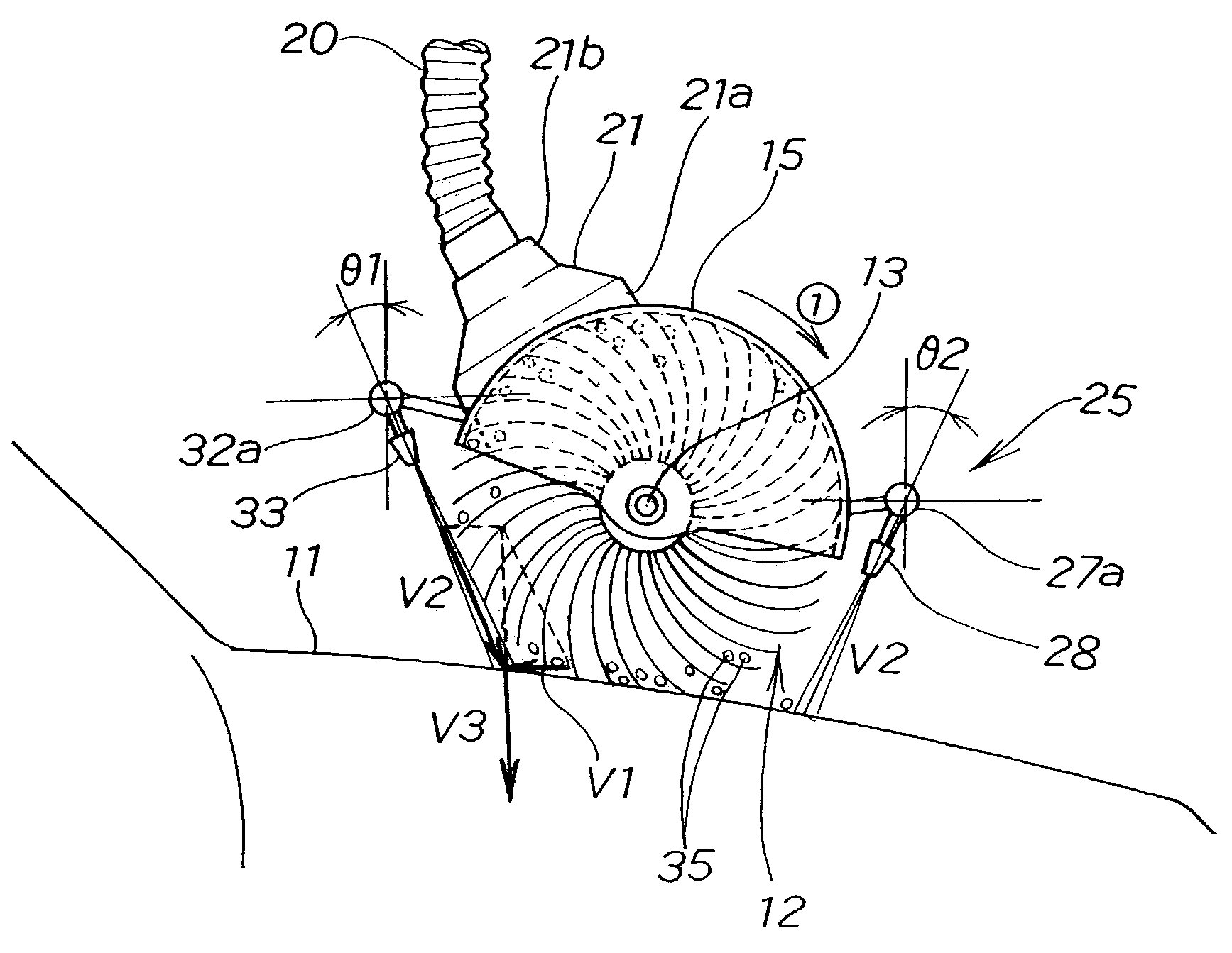
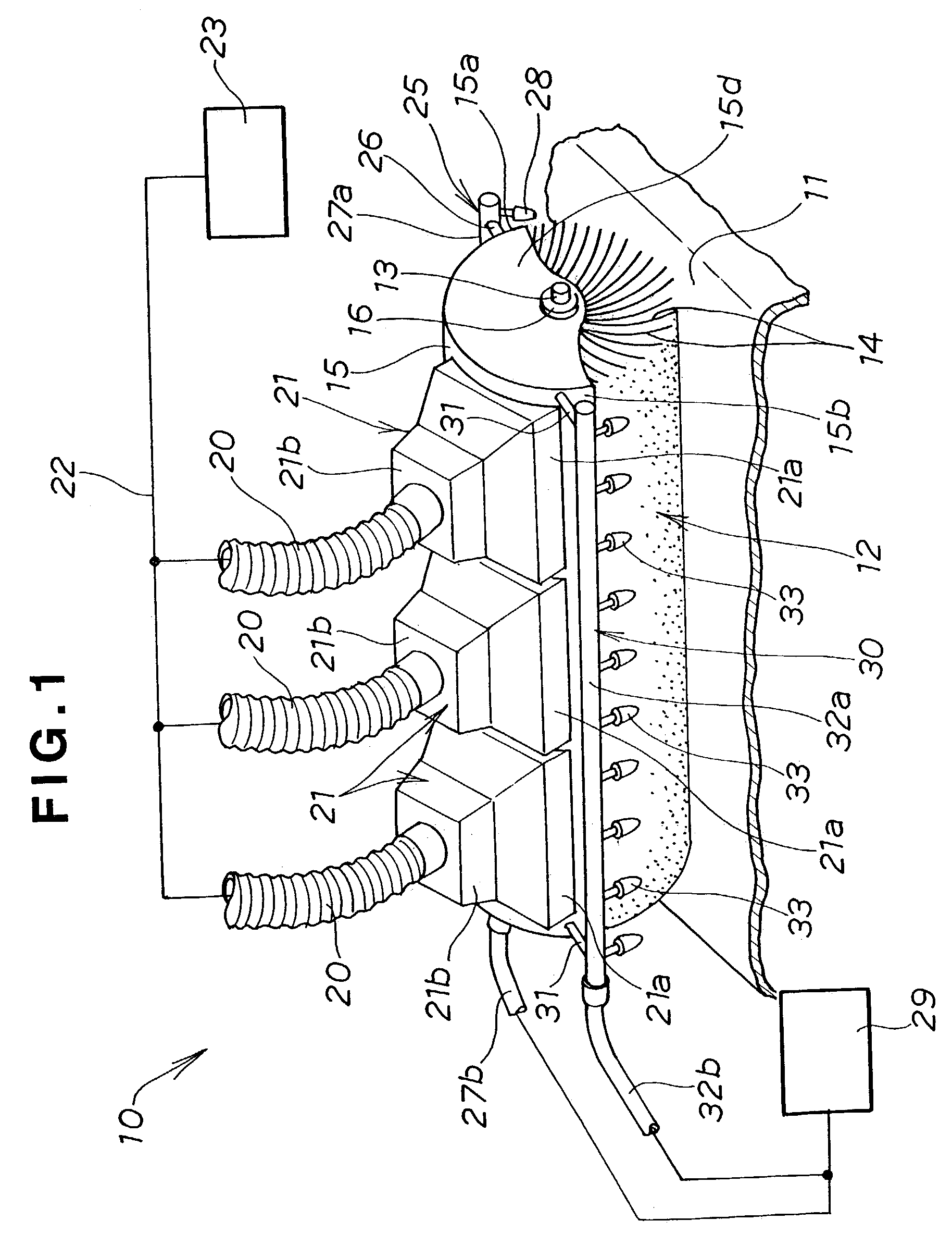
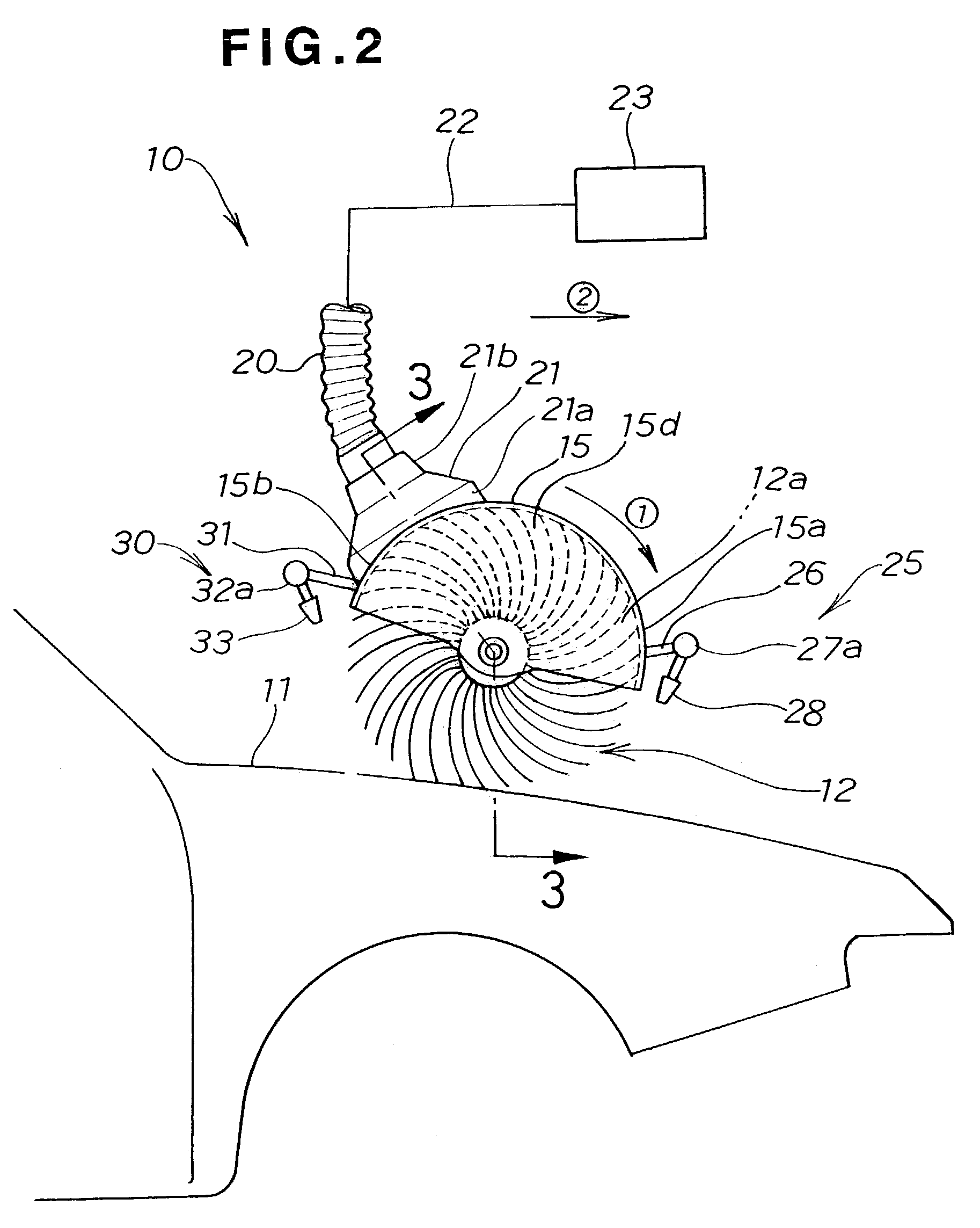
[0036]FIG. 1 is a perspective view of a dust removal apparatus in accordance with an embodiment of the present invention, and FIG. 2 is a side view of the dust removal apparatus of FIG. 1.

[0037]The dust removal apparatus 10 includes a rotary brush 12 mounted on and along a rotation shaft or hub 13 extending generally parallel to a surface 11 of a workpiece; the rotary brush 12 has a generally cylindrical contour extending perpendicularly to a front-and-rear direction of the apparatus 10. As will be described, the rotary brush 12 is movable in the front-and-rear direction. Upper half portion 12a of the rotary brush 12 is covered with a hood 15 of a semicylindrical shape defining a predetermined dust removing space. The hood 15 has a pair of opposed side surfaces each having a semicircular shape, and linear front and rear end edges 15a and 15b. A plurality of exhaust ducts 20 are connected to the hood 15 in a manner to be described later, and the dust removal apparatus 10 is designed ...


PUM


Abstract

In a dust removal apparatus, a front air nozzle unit emits air jets onto a region of a workpiece surface near a rotary brush along a linear front end edge of a hood covering an upper half portion of the rotary brush. Rear air nozzle unit emits air jets onto another region of the workpiece surface near the rotary brush along a linear rear end edge of the hood.

Description

FIELD OF THE INVENTION[0001]The present invention relates to dust removal apparatus for removing foreign dust particles, dirt particles, lint etc. (hereinafter generically referred to as dust particles) from the surface of a workpiece, before painting the surface in order to paint the workpiece surface in satisfactory condition.[0002]In painting a body surface of a motor vehicle, undesired painting defects may result unless dust particles present on the body surface are cleared prior to the painting. To avoid such painting defects, it is necessary to remove dust particles, adhering to the vehicle body surface, using a dust removal apparatus, before actually painting the vehicle body surface.[0003]Among various conventionally-known dust removal apparatus is one that is disclosed in Japanese Utility Model Laid-open Publication No. 62-132776, which will be discussed in detail below.[0004]FIG. 13 is a sectional view of the dust removal apparatus 100 disclosed in the utility model laid-o...

Claims


Application Information

Patent Timeline
IPC IPC(8): A47L5/14A46B13/00B05B1/14B08B1/04B08B5/02B08B5/04B08B15/04B60S3/06
CPCB08B1/04B60S3/06B08B15/04B08B5/02A46B13/001B08B1/32B05C9/10
Inventor IKEDA, HIDEKITSUKAHARA, HIDEAKIMIYAJIMA, SHINJIHONDA, SEIICHIINOMATA, EIJI
Owner HONDA MOTOR CO LTD
Learn More