
Multi-stage pusher centrifuge

Active Publication Date: 2006-03-28
FERRUM PROCESS SYST AG
View PDF13 Cites 3 Cited by
  • Summary
  • Abstract
  • Description
  • Claims
  • Application Information

AI Technical Summary

Benefits of technology

[0011]It is therefore an object of the present invention to provide an improved multi-pusher centrifuge which largely avoids the disadvantages known from the prior art.
[0012]In accordance with the invention, a multi-stage pusher centrifuge is provided for the separation of a mixture into a solid cake and into a liquid phase. The multi-stage pusher centrifuge includes an outer screen drum rotatable about an axis of rotation and at least one screen stage arranged in the outer screen drum, a mixture distributor arranged in the screen drum and having a pusher base apparatus, with either the screen stage or the pusher base being arranged and designed movably to and fro along the axis of rotation such that the solid cake can be displaced using the pusher base apparatus. The multi-stage pusher centrifuge further includes an infeed device with which the mixture can be introduced via the mixture distributor into an empty space which arises when the solid cake is displaced by the pusher base apparatus, with the pusher base apparatus including a pre-acceleration funnel which extends substantially divergently in the direction toward the infeed device and the pre-acceleration funnel being designed as a pre-acceleration screen.
[0013]Since the multi-state pusher centrifuge in accordance with the invention has a pre-acceleration screen arranged at the pusher base apparatus, the total amount of liquid phase contained in the supplied mixture does not have to be accelerated to the full peripheral speed of the screen drum, since some of the liquid phase is already separated via the pre-acceleration screen and can be removed from the screen drum. Mixtures with a very high liquid content can thus also be processed without problem. In particular, a uniform distribution of the mixture to be dried over the peripheral surface of the screen stage or of the screen drum is thus also always ensured even with a high liquid content.

Problems solved by technology

Although multi-stage pusher centrifuges such as briefly outlined above have also been well known for special applications in the most varied variants for a long time, the known multi-stage pusher centrifuges nevertheless show different serious disadvantages.
Even if lower inlet concentrations, i.e. mixtures with an increased liquid content, can be processed better with the known multi-stage pusher centrifuges than with customary single-stage pusher centrifuges, the inlet concentration of the mixture to be processed may not have any desired low degree.
With too high a liquid content, a uniform distribution of the mixture to be dried over the periphery of the screen drum is made increasingly difficult.
This can result, on the one hand, in very damaging vibrations of the screen drum and thus to premature wear of bearings and the drive; in the worst case even to a safety problem in operation.
On the other hand, a solid cake distributed unevenly over the periphery of the screen drum brings about problems in washing.
It is obvious that the use of such pre-dewatering systems is very complex and thus expensive both from a process and an apparatus point of view.
A further serious disadvantage in the processing of mixtures of a smaller inlet concentration consists of practically the whole volume of liquid supplied with the mixture having to be accelerated to the full peripheral speed before it is separated through the filter screen of the screen drum.
This is extremely unfavorable energetically and has a clearly negative influence on the operating behavior of the centrifuge.
But even in the processing of mixtures with a much higher solid concentration, the centrifuges known from the prior art have some huge disadvantages.
This can result, among other things, in grain breakage, in particular with sensitive substances; that is, for example, solid grains which are distributed in a suspension supplied to the centrifuge burst into smaller pieces in an uncontrolled manner on the abrupt acceleration process, which can have negative influences on the quality of the solid cake produced when, for example, the particle size of the grains in the end product plays a role.

Method used


Image

  • Multi-stage pusher centrifuge
  • Multi-stage pusher centrifuge
  • Multi-stage pusher centrifuge

Examples


Embodiment Construction

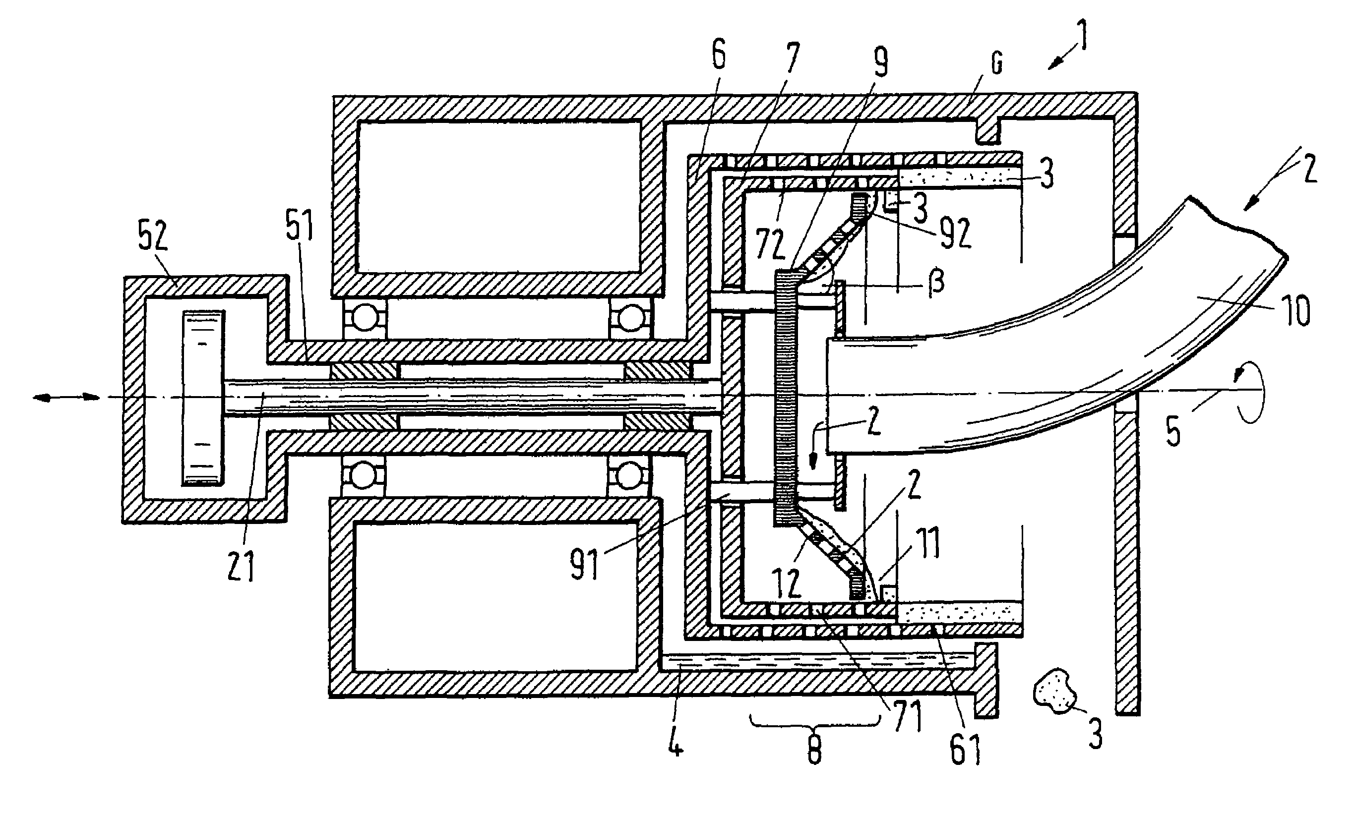
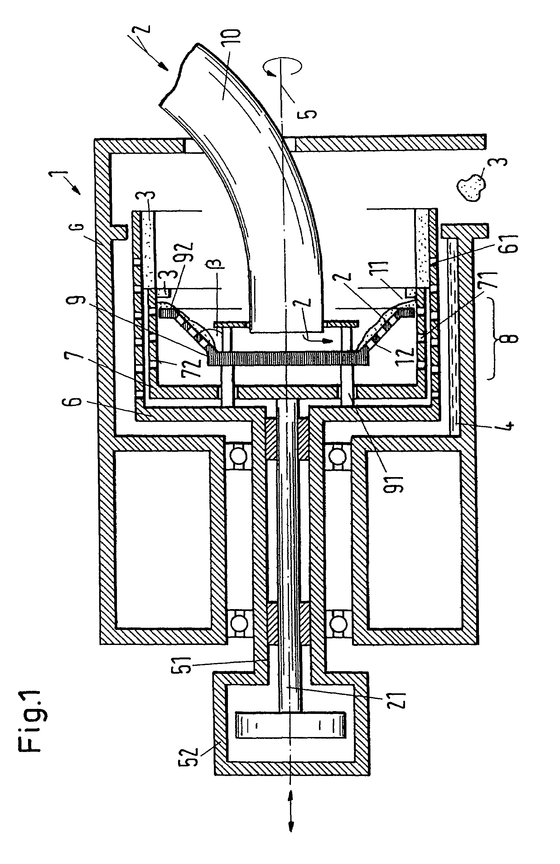
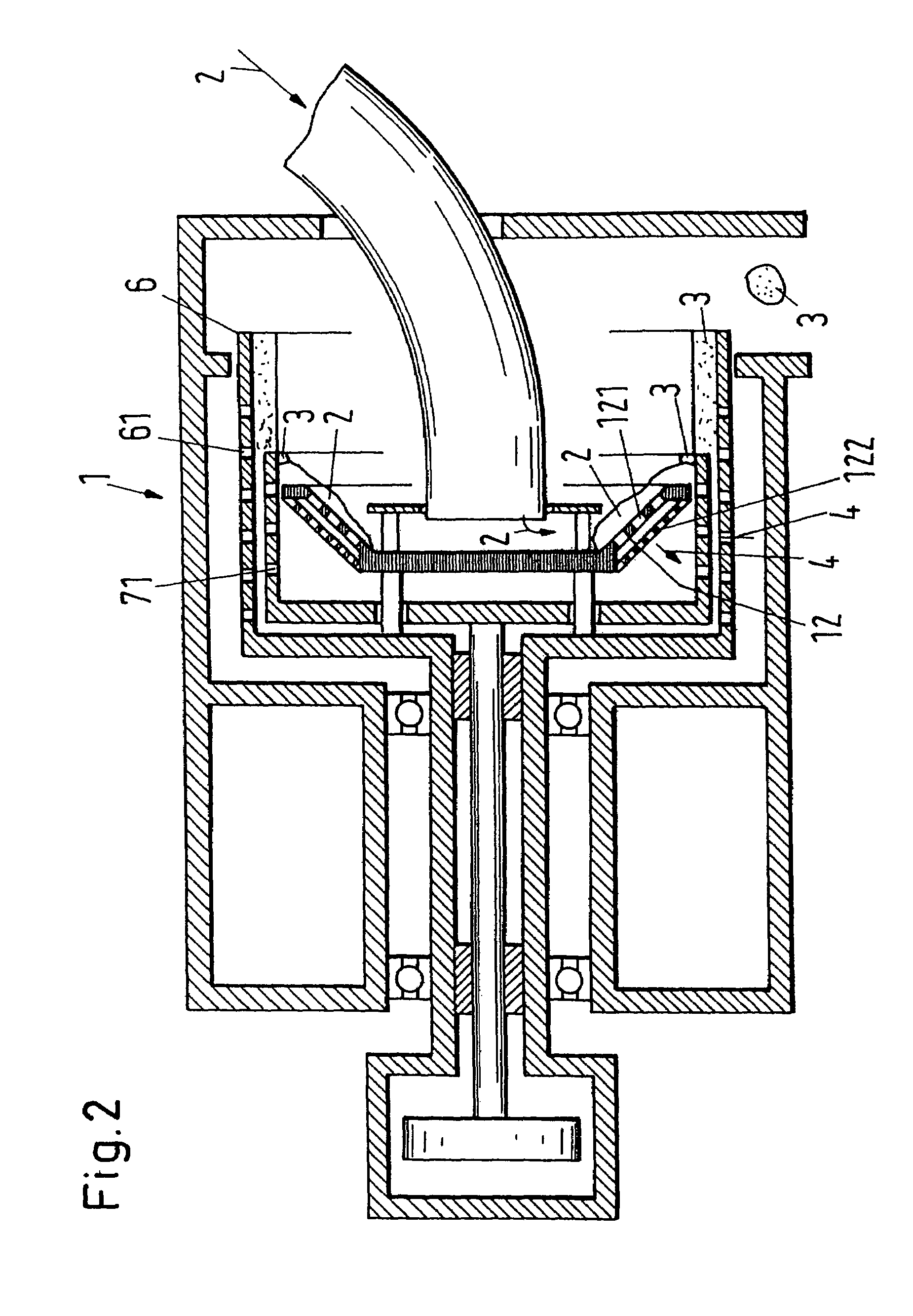
[0055]FIG. 1 shows, in section in a schematic representation, important components of a first embodiment of a multi-stage pusher centrifuge in accordance with the invention with a pre-acceleration screen. In the drawings of the present applications, for reasons of clarity, only two-stage pusher centrifuges are shown schematically by way of example. It is understood that the illustration of two-stage pusher centrifuges is to be understood as an example and that the description also applies to pusher centrifuges with more than two stages and can be transferred correspondingly.

[0056]The multi-stage pusher centrifuge in accordance with the invention, which will be designated as a whole in the following with the reference numeral 1, serves for the separation of a mixture 2 into a solid cake 3 and into a liquid phase 4 and includes as important components an outer screen drum 6 which is rotatable via a drum axle 51 about an axis of rotation 5 and is accommodated in a housing G. The drum a...


PUM

PropertyMeasurementUnit
Angleaaaaaaaaaa
Angleaaaaaaaaaa
Angleaaaaaaaaaa

Abstract

The invention relates to a multi-stage pusher centrifuge (1) for the separation of a mixture (2) into a solid cake (3) and into a liquid phase (4). The multi-stage pusher centrifuge (1) includes an outer screen drum (6) rotatable about an axis of rotation (5) and at least one screen stage (7) arranged in the outer screen drum (6), and a mixture distributor (8) arranged in the screen drum (6) with a pusher base apparatus (9), with either the screen stage (7) or the pusher base apparatus (9) being arranged movably to and fro along the axis of rotation (5) such that the solid cake (3) is displaceable by means of the pusher base apparatus (9). The multi-stage centrifuge further includes an infeed device (10) with which the mixture (2) can be introduced via the mixture distributor (8) into an empty space (11) which arises on the displacement of the solid cake (3) by the pusher base apparatus (9), with the pusher base apparatus (9) including a pre-acceleration funnel (12) which extends in a substantially divergent manner in the direction towards the infeed device (10) and the pre-acceleration funnel (12) being designed as a pre-acceleration screen (12).

Description

BACKGROUND OF THE INVENTION[0001]The invention relates to a multi-stage pusher centrifuge for the separation of a mixture into a solid cake and into a liquid phase, including an outer screen drum rotatable about an axis of rotation and at least one screen stage arranged in the outer screen drum, a mixture distributor arranged in the screen drum with a pusher base apparatus, with either the screen stage or the pusher base apparatus being arranged movably along the axis of rotation such that the solid cake is displaceable by means of the pusher base apparatus, and including an infeed device with which the mixture can be introduced via the mixture distributor into an empty space which forms when the solid cake is displaced by the pusher base apparatus.[0002]Centrifuges are widespread and are used in the most varied areas in the most varied embodiments for the drying of moist substances or of moist substance mixtures. Discontinuously operating centrifuges such as scraper centrifuges are...

Claims


Application Information

Patent Timeline
IPC IPC(8): B01D33/46B01D33/06B04B3/02B04B11/06
CPCB04B11/06B04B3/02
Inventor REINACH, HARALDGEIGER, ROY
Owner FERRUM PROCESS SYST AG
Learn More