Axial shaft seal

a technology of axial shaft and sealing plate, which is applied in the direction of instruments, mechanical devices, devices using electric/magnetic means, etc., can solve the problems of long service life and power loss, and achieve the effect of reliable sealing

Inactive Publication Date: 2006-03-28
CARL FREUDENBERG KG
View PDF8 Cites 12 Cited by
  • Summary
  • Abstract
  • Description
  • Claims
  • Application Information

AI Technical Summary

Benefits of technology

[0004]An object of the present invention is to design an axial shaft seal so that a reliable seal is achieved even with great axial play and radial deflection of the shaft in particular. The seal should also have the simplest possible design and should permit easy assembly.

Problems solved by technology

It has a lower power loss and thus there is almost no coking of oil, so this results in a long service life.

Method used


Image

  • Axial shaft seal
  • Axial shaft seal
  • Axial shaft seal

Examples


Embodiment Construction

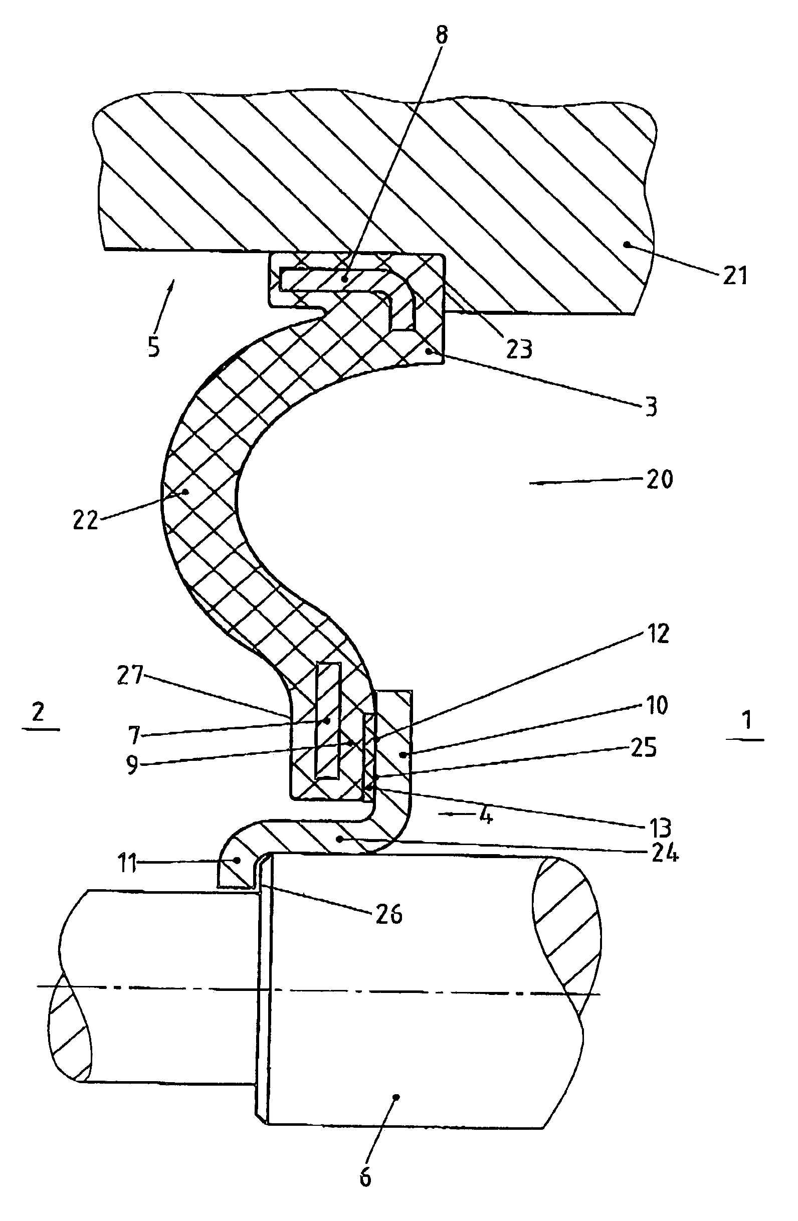
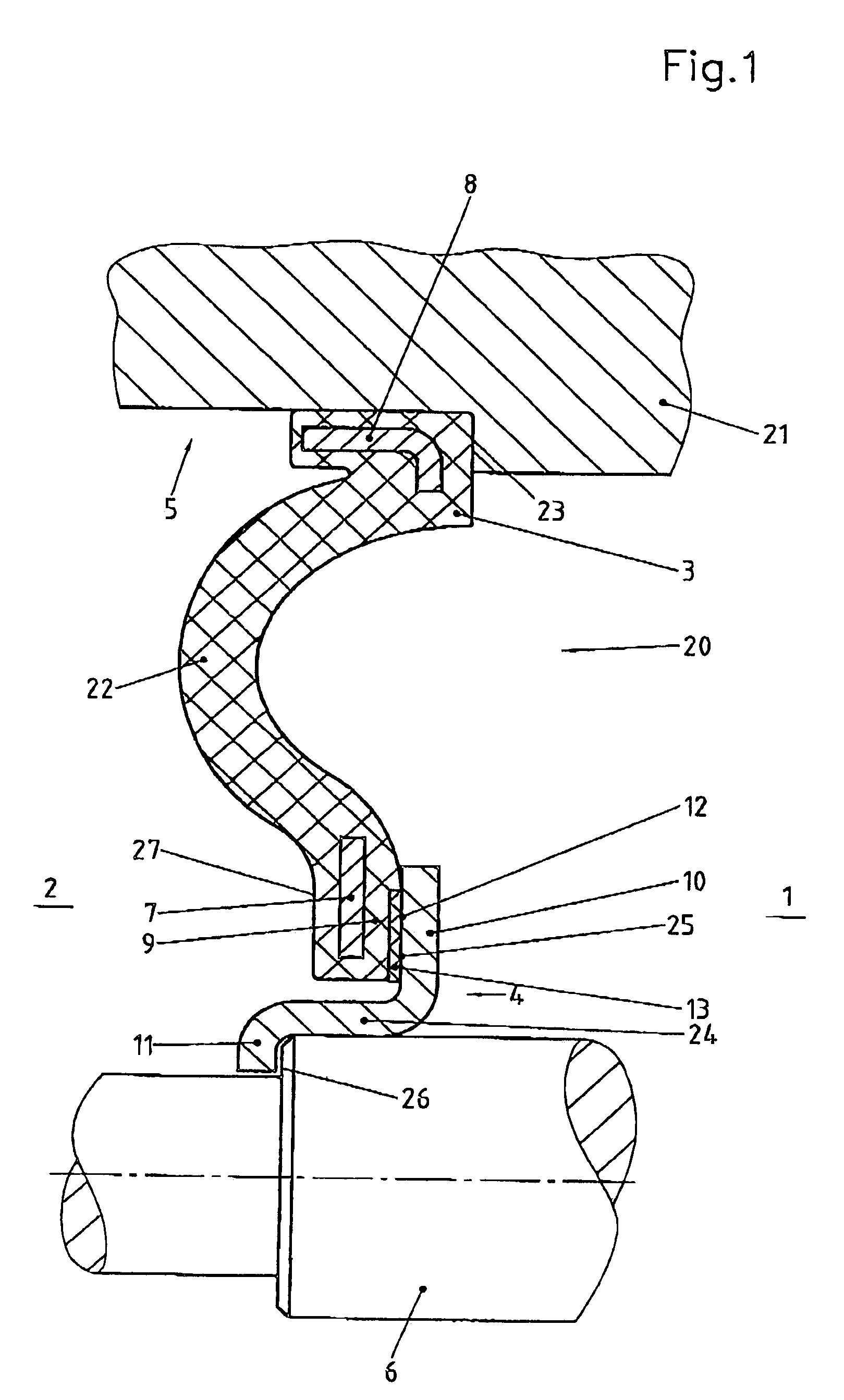
[0018]FIG. 1 shows a sectional view of an axial shaft seal 20 inserted into housing wall 21, sealing the gap between housing wall 21 and shaft 6. Axial shaft seal 20 is composed of two parts, namely outer ring 3, which is insertable into housing wall 21 in a stationary and sealing position, and inner ring 4. Outer ring 3 has a radially inward-directed sleeve 22 made of a polymer material in the shape of a spring bellows. Inside sleeve 22 is designed as a radial projection and has sealing face 13. To increase the rigidity of outer ring 3 or inside edge 9, they may be provided with reinforcements of a tough, hard material 8 and / or 7 in the form of a ring. Bore 5 in housing 21 is provided with a shoulder 23 forming a stop at which outer ring 3 comes to rest.

[0019]Inner ring 4 is placed on shaft 6. It has a cylindrical middle part 24 and a ring flange 10 directed radially outward and having mating sealing face 25 for sealing face 13 of inside edge 9 of sleeve 22. Inner ring 4 is placed ...


PUM


Abstract

An axial shaft seal disposed between a housing wall and a rotating shaft includes an outer ring insertable into the housing wall in a stationary and sealing manner and an inner ring connectable to the shaft in a non-twisting and sealing manner. The outer ring includes a sleeve having a polymer material extending radially inward and having a spring bellows form. A radially inward end portion of the sleeve has a first sealing surface. The inner ring includes a ring flange extending radially outward so as to provide a second sealing surface for axially mating the first sealing face.

Description

[0001]Priority is claimed to German patent application no. DE 102 28 621.3, filed on Jun. 26, 2002, the subject matter of which is incorporated by reference herein.BACKGROUND[0002]The present invention relates to an axial shaft seal between a housing wall or the like and a shaft rotating therein. Such axial shaft seals are known in various embodiments. Their different designs are usually due to the fact that there are special scaling problems. One of these problem cases is in achieving a seal even when the rotating shaft executes substantial axial movements.[0003]German utility model DE 1 893 773 describes an axial shaft seal in which the axial sealing ring of the seal also moves to a slight extent with an axial displacement of the shaft. Therefore, a soft and relatively long seal is achieved. However, this axial seal necessitates a shaft collar being placed on the shaft, so that the sealing lip rests on it, or a shoulder at the end of the shaft, forming an end face for the sealing ...

Claims


Application Information

Patent Timeline
Patent Type & Authority Patents(United States)
IPC IPC(8): F16J15/32F16J15/34F16J15/36G01P3/44
CPCF16J15/3264G01P3/443F16J15/36F16J15/3456
Inventor KLENK, THOMASBOCK, EBERHARDKRAMER, THOMASHUFNAGEL, WERNERHELDMANN, MARTINCLEMENS, MARKUSPATAILLE, GILBERT
Owner CARL FREUDENBERG KG
Why Eureka
Try Eureka