Method of minimizing the gap between a rotating turbine blade and a casing of a turbine, a turbine, and a method of determining the wear behavior of a wheel of a rotor

a technology of a rotating turbine blade and a casing, which is applied in the direction of rotors, instruments, liquid fuel engines, etc., can solve the problems of insufficient accuracy and/or considerable equipment investment in the direction of methods, and achieve the effect of minimizing the gap between the wheel and the casing in a simple manner

Inactive Publication Date: 2006-03-28
SIEMENS AG
View PDF12 Cites 13 Cited by
  • Summary
  • Abstract
  • Description
  • Claims
  • Application Information

AI Technical Summary

Benefits of technology

[0008]It is therefore an object of the invention to show a method with which the gap between wheel and casing is minimized in a simple manner.

Problems solved by technology

However, the methods require considerable outlay in terms of equipment and / or are not very accurate, so that further optimization is desirable.

Method used


Image

  • Method of minimizing the gap between a rotating turbine blade and a casing of a turbine, a turbine, and a method of determining the wear behavior of a wheel of a rotor
  • Method of minimizing the gap between a rotating turbine blade and a casing of a turbine, a turbine, and a method of determining the wear behavior of a wheel of a rotor
  • Method of minimizing the gap between a rotating turbine blade and a casing of a turbine, a turbine, and a method of determining the wear behavior of a wheel of a rotor

Examples


Embodiment Construction

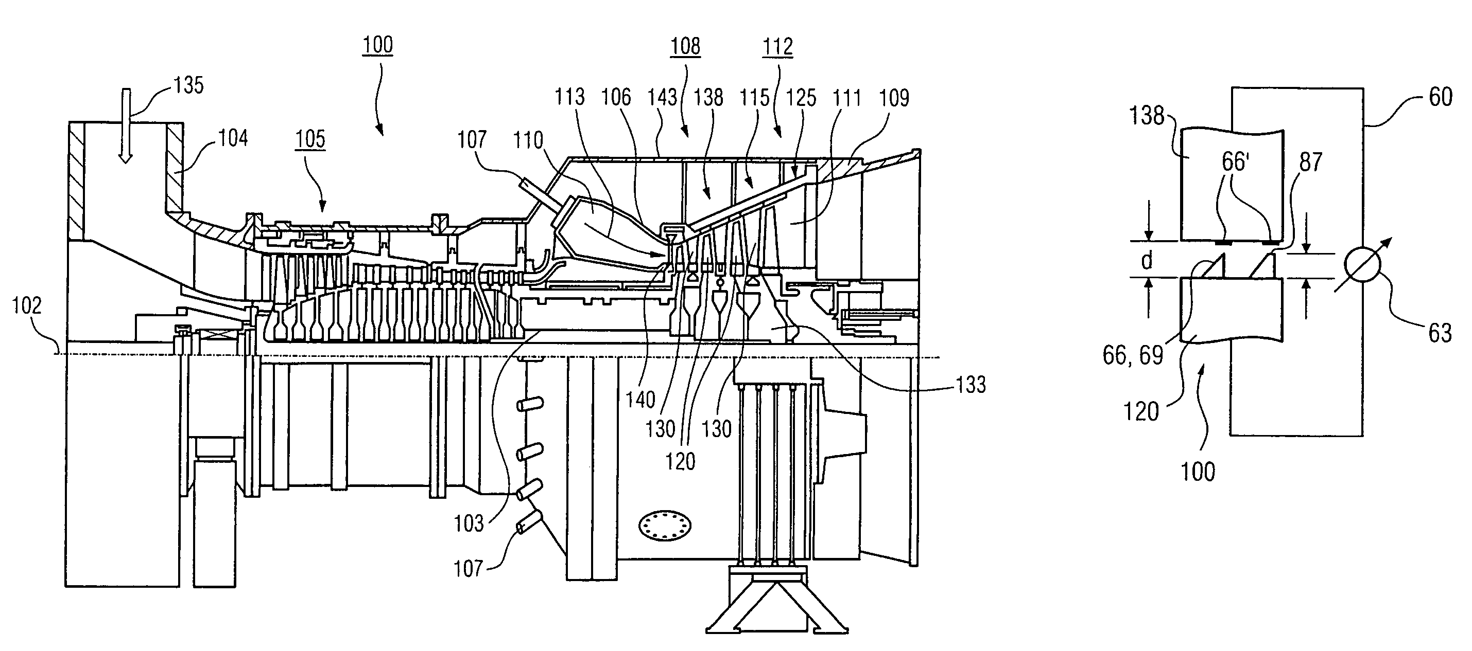
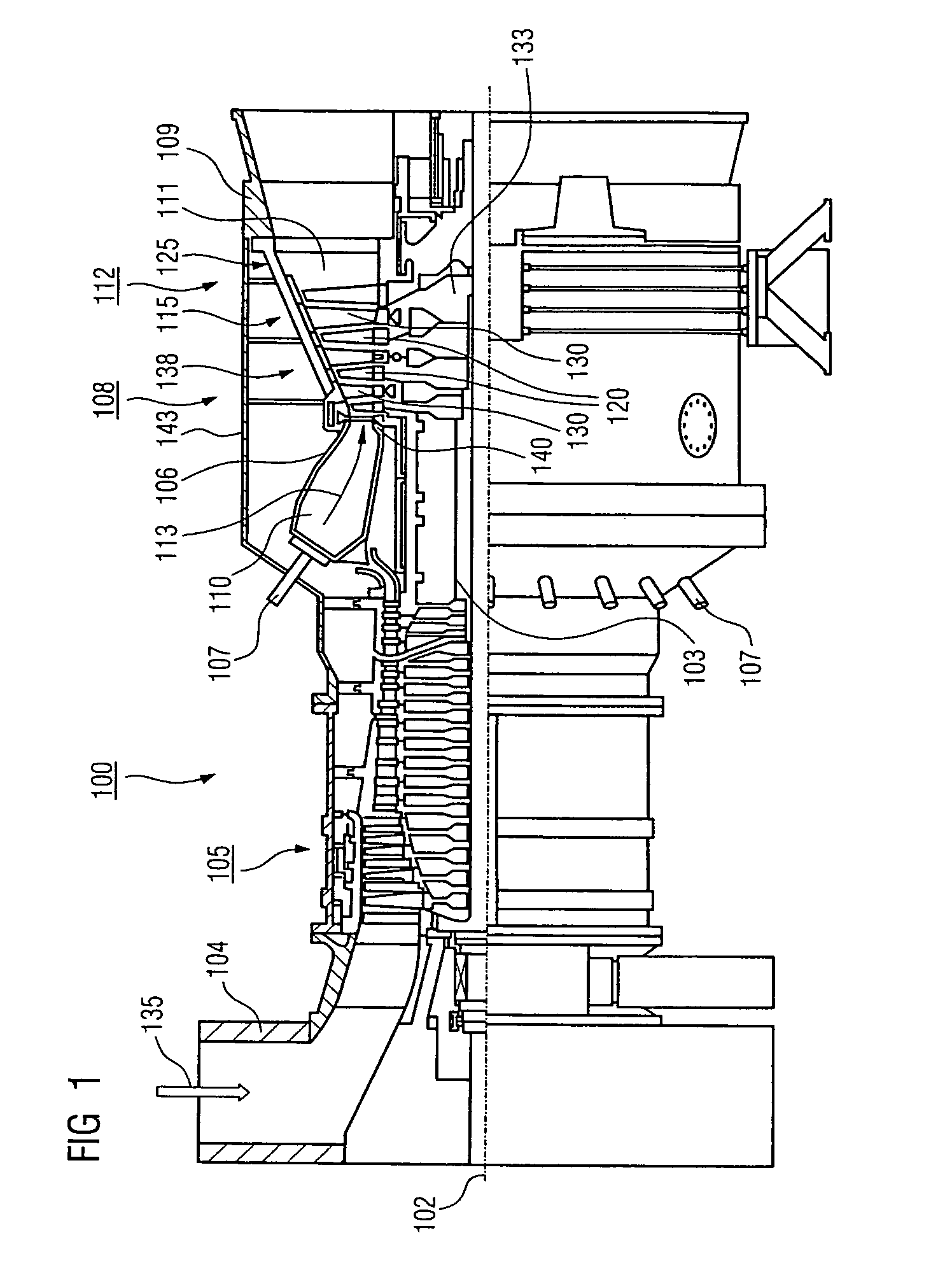
[0022]FIG. 1 shows a gas turbine 100 in a longitudinal partial section.

[0023]In the interior, the gas turbine 100 has a rotor 103 which is rotatably mounted about a rotation axis 102 (axial direction) and is also designated as turbine wheel. Following one another along the rotor 103 are an intake casing 104, a compressor 105, a, for example toroidal, combustion chamber 110, in particular an annular combustion chamber 106, having a plurality of coaxially arranged burners 107, a turbine 108 and the exhaust-gas casing 109. The annular combustion chamber 106 communicates with a, for example annular, hot-gas duct 111. The turbine 108 is formed there by, for example, four turbine stages 112 arranged one behind the other. Each turbine stage 112 is formed from two blade rings. As viewed in the direction of flow of a working medium 113, a row 125 formed from moving blades 120 follows a guide-blade row 115 in the hot-gas duct 111.

[0024]In this case, the guide blades 130 are fastened to the st...


PUM


Abstract

Method of minimizing the gap between a wheel and a casing of a turbine, a turbine, and a method of determining the wear behavior of a wheel of a rotor. To minimize the gap between a wheel and a casing in a turbine, optical methods are also often used in order to minimize the gap. However, this is very expensive. The method according to the invention proposes that the wheel and the casing (be part of an electric circuit, so that an electrical parameter, such as resistance for example, can be measured, the value of which shows whether a contact is present.

Description

CROSS REFERENCE TO RELATED APPLICATION[0001]This application claims priority of the European application No. 03023207.8 EP filed Oct. 13, 2003 under the European Patent Convention and which is incorporated by reference herein in its entirety.FIELD OF THE INVENTION[0002]The invention relates to a method of minimizing the gap between a wheel and a casing of a turbine according to the preamble the claims and to a turbine according to the preamble of the claims and to a method of determining the wear behavior of a wheel of a rotor as claimed in the claims.BACKGROUND OF THE INVENTION[0003]In a turbine, such as a steam or gas turbine for example, a rotor having at least one disk and a plurality of blades rotates inside a casing. There is a gap between the blade end and the casing.[0004]Methods of displacing rotor and wheel have been disclosed by DE 42 23 495 and WO 00 / 28190.[0005]In order to achieve a high efficiency, the gap between blade end and casing is to be minimal.[0006]Methods of ...

Claims


Application Information

Patent Timeline
Patent Type & Authority Patents(United States)
IPC IPC(8): F01D11/14F01D11/22F01D21/04
CPCF01D21/04F01D11/22
Inventor MILAZAR, MIRKO
Owner SIEMENS AG
Why Eureka
Try Eureka