
Method of optimizing processing of successive workpieces through cutting machines

Inactive Publication Date: 2006-10-05
USNRKOCKUMS CANCAR
View PDF17 Cites 13 Cited by
  • Summary
  • Abstract
  • Description
  • Claims
  • Application Information

AI Technical Summary

Benefits of technology

[0006] The present invention reduces the gap between successive workpieces by modifying the optimized cutting solution or the optimized cut pattern between successive workpieces such that re-adjustment and re-positioning of the cutting devices between successive workpieces may be minimized, thereby reducing the gap required between the workpieces. The gap between successive workpieces may also be reduced by transmitting the optimized cut pattern of a succeeding workpiece to the positioner of the cutting device before the cutting device completes processing a preceding workpiece such that the cutting device may commence to re-adjust and re-position shortly before or as soon as the cutting device completes processing the preceding workpiece.
[0008] In one embodiment of the invention, the optimizer determines an optimized cutting solution for each of the successive workpieces and the processor determines an optimized cut pattern based on the optimized cutting solution. The optimized cut pattern may be transmitted to the positioners of the cutting device before the cutting device exits the workpiece being processed and the cutting device may be immediately adjusted and positioned for example slightly before or as soon as the cutting device completes processing and exits the preceding workpiece. The ability to immediately re-adjust and re-position the cutting device therefore reduces the gap between successive workpieces. The immediate re-adjustment and re-positioning also eliminates time lost waiting for the next succeeding optimized cut pattern to be transmitted to the positioner of the cutting device and the ensuing transition time to adjust the cutting device. As such, productivity and throughput of the workpiece processing system may be increased without compromising recovery. Thus, the succeeding optimized cut pattern may be transmitted to the positioner of the cutting device such that the cutting device may begin adjusting and positioning according to the succeeding optimized cut pattern of the succeeding workpiece during the cutting device exiting, that is, as the cutting device begins to exit the preceding workpiece where a characteristic such as blade flexibility allows the processor to assess and balance the amount of re-adjustment and re-positioning required between successive workpieces and determine if the cutting device may be able to withstand some or all of the required re-adjustment and re-positioning before the cutting device exits the preceding workpiece. The ability to re-adjust and re-position the cutting device before the cutting device completes processing the preceding workpiece enables the cutting device to begin processing the succeeding workpiece according to the succeeding optimized cut pattern sooner, for example immediately, thereby significantly reducing or even eliminating the gap between the successive workpieces. As such, productivity and throughput of the workpiece processing system may be increased without significantly or at all compromising recovery.
[0009] In another embodiment of the invention, prior to the cutting device engaging and processing the workpieces, the optimizer compares the optimized cutting solution of the preceding workpiece with the optimized cutting solution of the succeeding workpiece. The processor may decide to modify the cut pattern of either the preceding or the succeeding workpiece or both such that minimal or no re-adjustment or re-positioning of the cutting device is required between the lead-out segment and the lead-in segment of the successive workpieces. As such, the gap between the successive workpieces may be significantly reduced or eliminated, thereby increasing throughput of the workpiece processing system. The decision to modify the cut pattern of either the preceding or succeeding workpiece depends on the impact the decision has on recovery.
[0010] In yet another embodiment of the invention, prior to the cutting device engaging and processing the workpieces, the optimizer compares the optimized cutting solution of the preceding workpiece with the optimized cutting solution of the succeeding workpiece. The optimizer may then re-optimize either the preceding or succeeding workpiece or both to re-adjust the optimized cutting solution such that adjustments of the cutting devices between successive workpieces are minimal. As such, successive workpieces may be positioned very closely together such that the gap between the workpieces may be significantly reduced or even eliminated, thereby increasing the productivity and throughput of the workpiece processing system. The decision to re-optimize either the preceding or succeeding workpiece depends on the impact the decision has on recovery.
[0011] Preferably, the processor may be provided with wood value inputs such that the processor may compute and assess the costs and benefits of valuing volume or recovery, given the value inputs. The present invention may apply to straight sawing systems, curve sawing systems, or any workpiece processing system wherein the cutting devices are constantly re-adjusted and re-positioned between successive workpieces.

Problems solved by technology

This requires an increased gap between successive workpieces.
The problem with this gapping is that the productivity of the workpiece processing system is unnecessarily compromised.
Large gaps between successive workpieces lower the throughput of the workpiece processing system, thereby lowering the volume of production.

Method used


Image

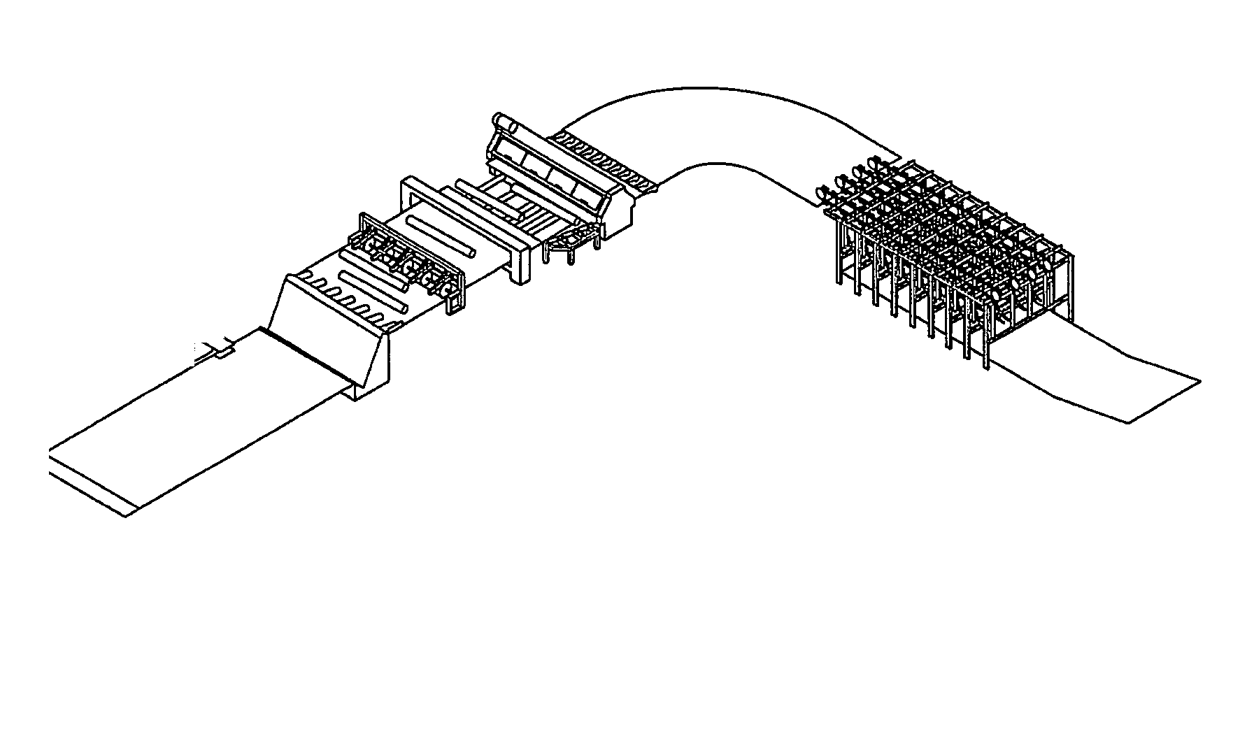
  • Method of optimizing processing of successive workpieces through cutting machines
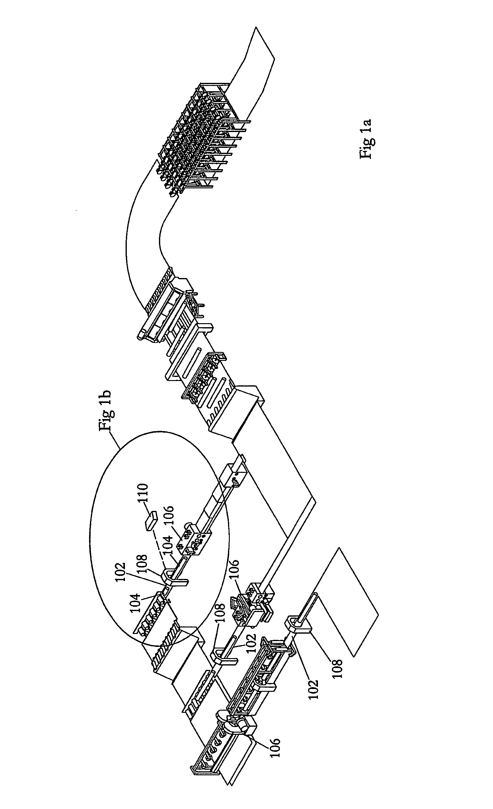
  • Method of optimizing processing of successive workpieces through cutting machines
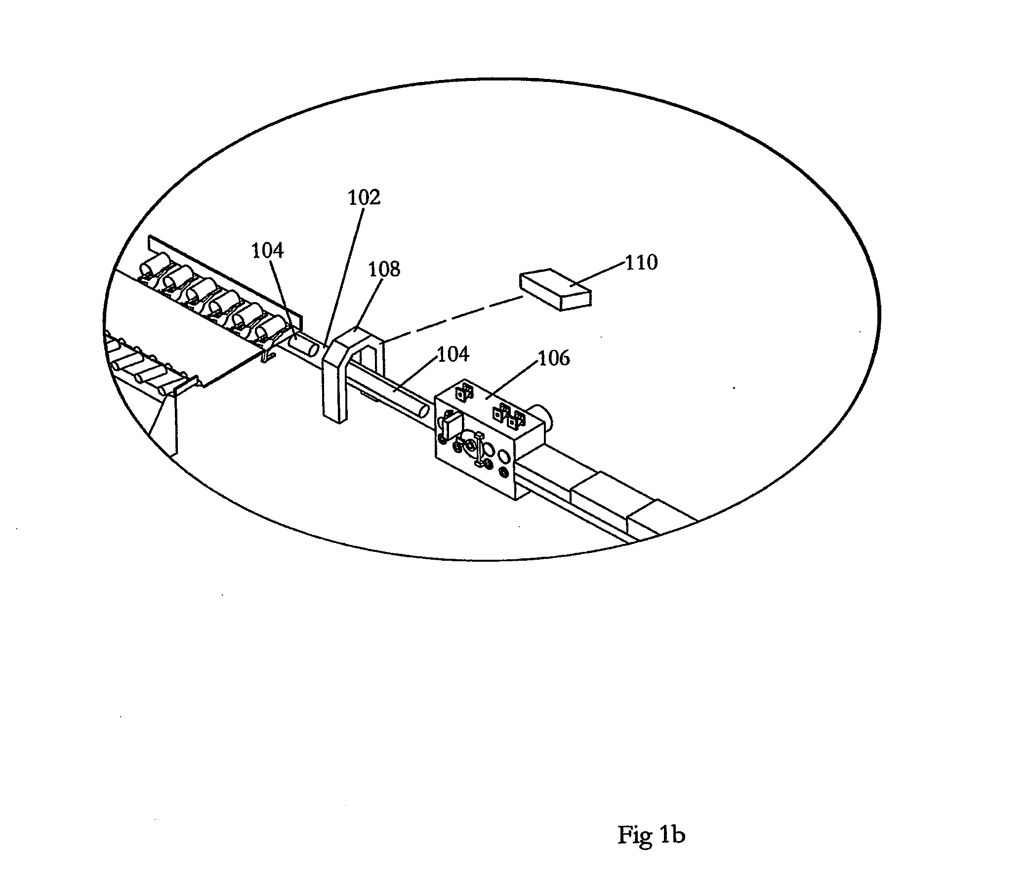
  • Method of optimizing processing of successive workpieces through cutting machines

Examples


second embodiment

[0026] In the method according to the present invention, as illustrated in the flow chart of FIG. 3 the optimizer determines an optimized cutting solution for successive workpieces independent of the optimized cutting solution of the preceding or subsequent next (that is, first subsequent) workpiece 10. The processor independently determines the optimized cut pattern to be followed by the cutting devices for each of the workpieces 15. Prior to processing the preceding workpiece, the cutting device motion is started and the cutting device is pre-positioned according to a first optimized cut pattern of the preceding workpiece 20. While the preceding workpiece is being processed 25, the optimized cut pattern of the succeeding workpiece is transmitted to the positioners of the cutting device before the cutting device completes the lead-out segment of the workpiece being processed 30 such that the cutting device may begin re-adjusting and re-positioning according to the succeeding optimi...

third embodiment

[0027] In the method according to the present invention, as set out in the flow chart of FIG. 4, prior to the cutting devices engaging and processing the workpieces, the optimizer compares the optimized cutting solution of the preceding workpiece with the optimized cutting solution of the succeeding workpiece 50 to determine a modified cut pattern. Preferably, the modified cut pattern is merely a modification of just the lead-in segment of the succeeding workpiece or just the lead-out segment of the preceding segment, or of both lead-in and lead-out segments such that adjustments between the successive workpieces may be minimized 55. The processor may decide to process the first workpiece according to the optimized cut pattern for that workpiece, but may decide to process the subsequent workpiece according to a modified cut pattern of the lead-in segment such that minimal or no re-adjustment or re-positioning of the cutting devices is required to adjust the optimized cut pattern of ...

fourth embodiment

[0028] In the method according to the present invention, as set out in the flow chart of FIG. 5, prior to the cutting devices engaging and processing the workpieces, the optimizer compares the optimized cutting solution of the preceding workpiece to be processed with the optimized cutting solution of the succeeding workpiece 50. The optimizer may then re-optimize the preceding workpiece 75 and process the preceding workpiece according to a re-optimized cut pattern 80 such that the cutting devices require minimal or no positioning between successive workpieces 85. Alternatively, the preceding workpiece may be processed according to the optimized cut pattern for that workpiece while the optimizer re-optimizes for the succeeding workpiece 75 to determine a re-optimized cutting solution such that the cutting devices require minimal or no positioning between successive workpieces 80. Whether or not the preceding workpiece or the succeeding workpiece is re-optimized, the optimized cut pat...


PUM

PropertyMeasurementUnit
Sizeaaaaaaaaaa
Flexibilityaaaaaaaaaa

Abstract

A method of optimizing processing of successive workpieces through cutting machines, includes the steps of determining and optimizing a first cut pattern for a preceding workpiece infeeding into an active cutting device, determining and optimizing a second cut pattern for a succeeding workpiece succeeding the preceding workpiece infeeding into the cutting device, synchronizing the preceding workpiece with the active cutting device such that the active cutting device is pre-positioned to achieve an optimized first cut pattern of the preceding workpiece prior to the preceding workpiece engaging the active cutting device, processing through the cutting device the preceding workpiece according to the first cut pattern; adjusting an infeed gap between the preceding workpiece and the succeeding workpiece so that the active cutting device has sufficient time to pre-position to achieve the optimized second cut pattern of the succeeding workpiece prior to the active cutting device engaging the succeeding workpiece.

Description

FIELD OF THE INVENTION [0001] This invention relates to the field of lumber manufacturing and in particular, it relates to a method for optimizing processing of successive lumber workpieces in through lumber processing machinery, and in particular cutting machines, by selectively adjusting the gap between the workpieces according to an optimized or re-optimized cutting and gapping solution. BACKGROUND OF THE INVENTION [0002] During the lumber manufacturing process, stems of wood, logs, cants, flitches, and other lumber workpieces are transported through various primary and secondary break down and processing systems, such as debarkers, merchandisers, edgers, and planers. Prior to being processed, workpieces are typically transported downstream along various log handling systems, such as a conveyor or feeder, before the workpieces make contact with the cutting devices of a workpiece processing system. For example, a stem of wood may be advanced downstream on a conveyor through a log ...

Claims


Application Information

Patent Timeline
IPC IPC(8): B26D3/00
CPCB27B31/06B27B1/007Y10T83/0538
Inventor POBUDA, RONALDWEBSTER, SANDYSTROUD, BRIANDAVYDUKE, ROLAND
Owner USNRKOCKUMS CANCAR
Learn More