[0011]In view of the above-mentioned problems, an object of the present invention is to provide a display device capable of freely setting a viewpoint (angle) from which an image formed by an imaging optical system of real specular image is seen.
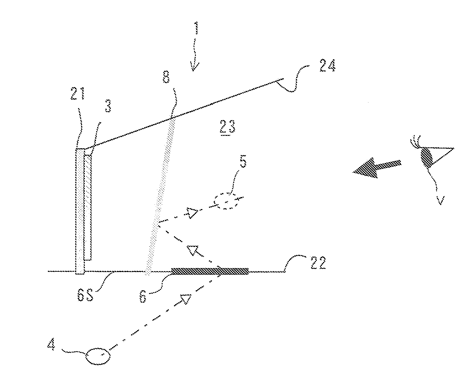
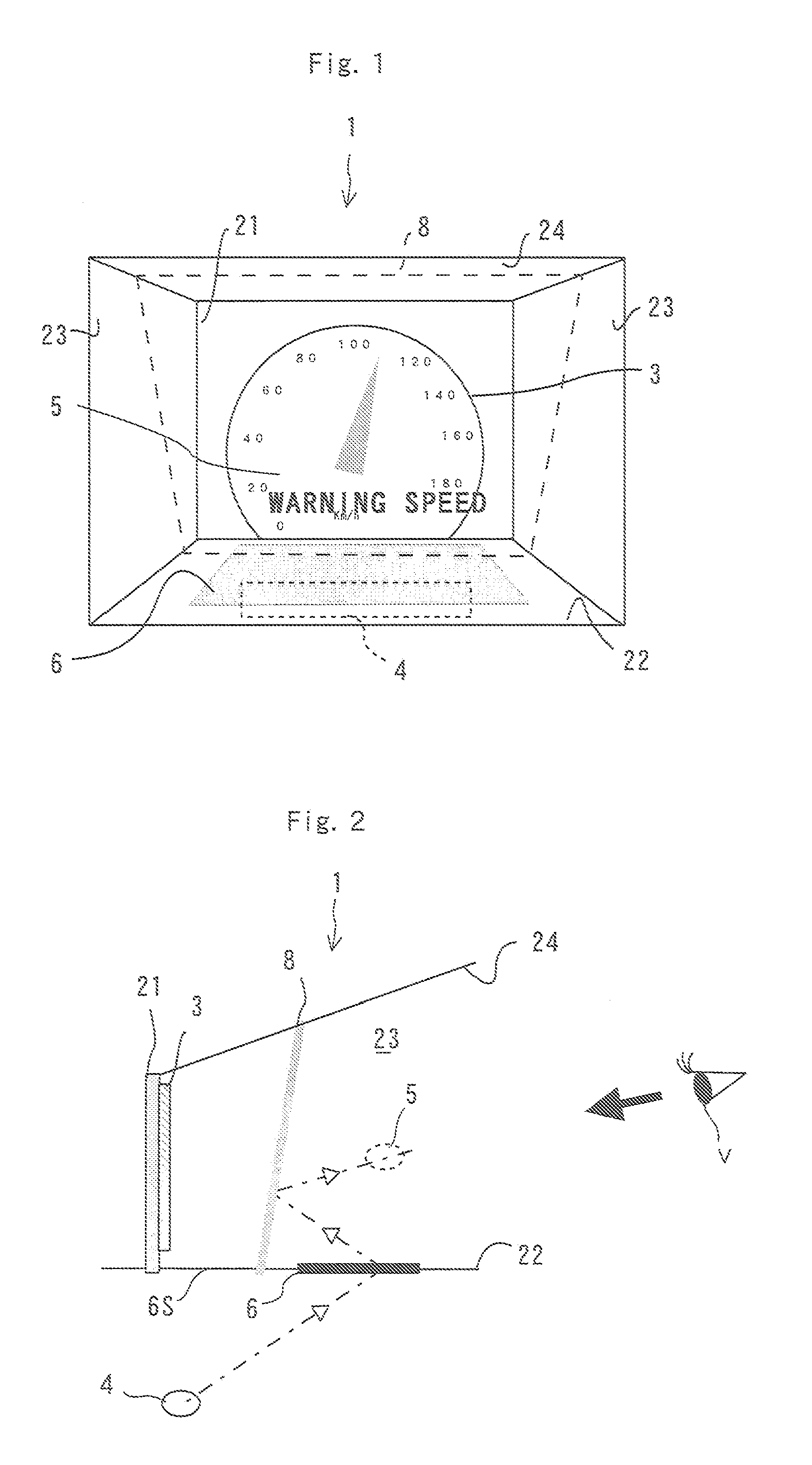
[0015]Variation of the positional relationship thereamong with time results in change of the position of a floating image with time. Specifically, if the object is moved along a line connecting the object and the imaging optical system of real specular image, an image may be formed at various positions. Accordingly, an image to be formed by the first half mirror surface may gradually be changed from a completely
virtual image to a completely real image, thereby making an image to be seen more impressive.
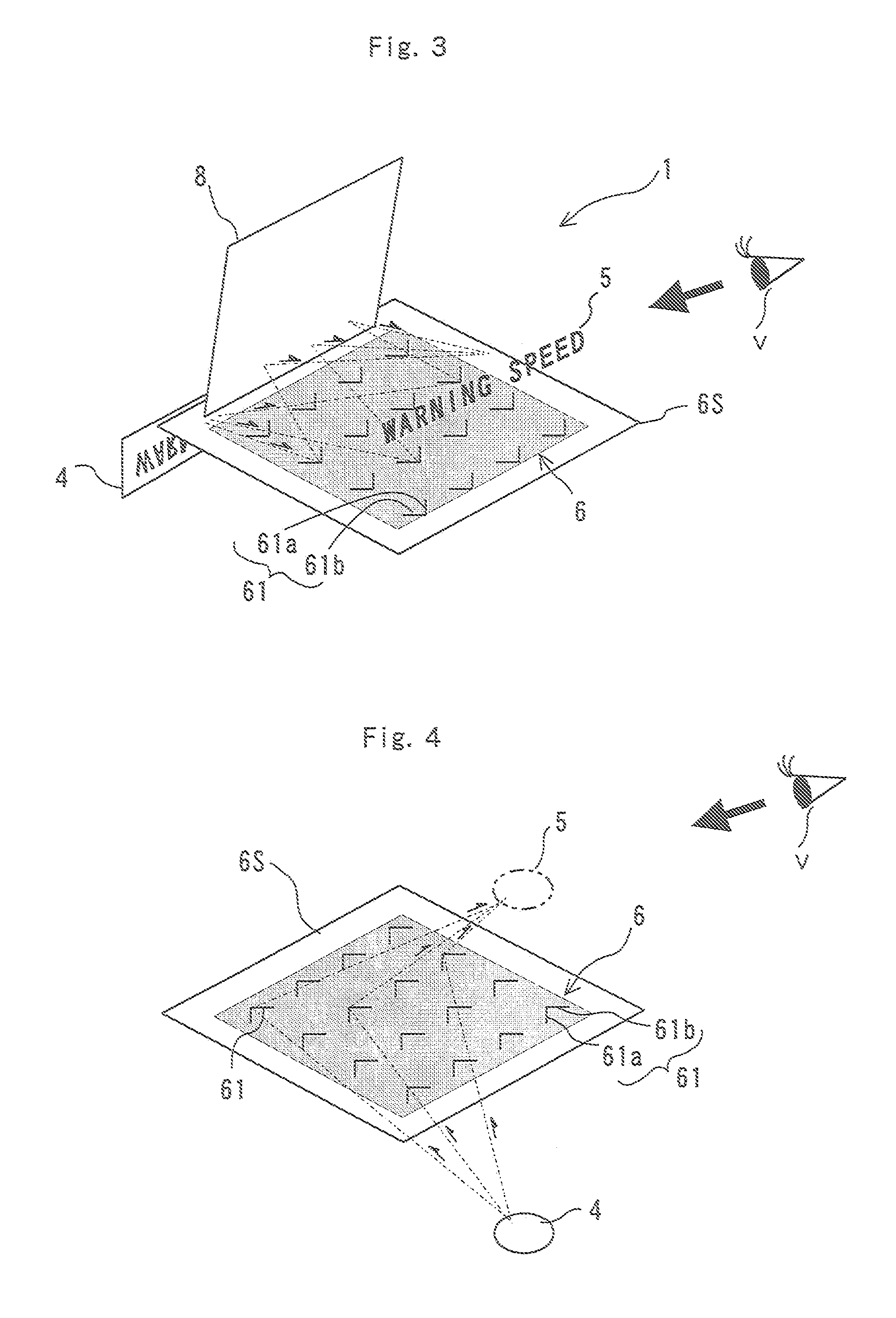
[0022]A shape of the optical hole should be considered, wherein all of the adjacent inner wall surfaces are orthogonal, as in a cube or a rectangular parallelepiped. In such a case, the gaps between adjacent dihedral corner reflectors can be minimized, and thereby highly dense arrangements are possible. It is preferable that reflection be prevented by a surface other than that of a dihedral
corner reflector that faces an object of view.
[0023]In the case where a dihedral
corner reflector has a plurality of inner mirror surfaces, some of the
transmitted light may undergo multiple reflections, i.e., there may occur multiple reflections of light beams passing through the hole several times or more than that of assumed reflections. Regarding countermeasures for these multiple reflections, if two mutually orthogonal mirror surfaces are formed on the inner wall of an optical hole, such multiple reflection is prevented in the following ways. In one way, a surface other than these two mirror surfaces may be made non-specular to prevent reflection of light beams by this surface. In another way, a surface other than these mirror surfaces may be tilted from an element surface so that it may not orthogonal to the element surface, or may be curved. In either way, generation of the multiply reflected
light beam reflected three times or more may be reduced, or prevented. In order to form a non-
specular surface, the following configuration may be used in which a
target surface may be coated with an anti-reflection
coating or a thin film and, alternatively, the
surface roughness of the
target surface may be increased to cause
diffuse reflection on the
target surface. In addition, the existence of a transparent and flat substrate does not obstruct the functions of the optical element, and therefore any appropriate substrate may be used as a supporting member and / or a protective member.
[0024]In order to enhance the brightness level of a real image to be projected, it is desirable that a number of dihedral corner reflectors arranged on an element surface are as close as possible to each other. As an example, lattice arrangement of the dihedral corner reflectors is effective. Such an arrangement makes it easy to manufacture a display device, as a merit. Amirror surface of each dihedral
corner reflector may be a flat surface for causing reflection of light beams, and which is made of a lustrous substance such as
metal or resin, regardless of whether the substance is
solid or liquid. A mirror surface of a dihedral corner reflector may also be such that it causes reflection or total reflection at a flat boundary interface between transparent media of different refractive indexes. In the case where a
total internal reflection is used for the mirror surface, it is highly likely that the undesirable multiple reflections by the plurality of multiple mirror surfaces will exceed the critical angle of the
total internal reflection, and therefore it is expected that these undesirable multiple reflections will naturally be suppressed. Additionally, the mirror surface may either be formed only on a limited part of the inner wall of an optical hole, or may be constructed of a plurality of unit mirror surfaces arranged in parallel, as long as each mirror surface serves its function without problems. Regarding the latter aspect, in other words, the formation of a mirror surface from unit mirror surfaces means that a mirror surface may be divided into a plurality of unit mirror surfaces. In this case, the unit mirror surfaces are not necessarily required to exist on the same plane, but are parallel. Furthermore, the unit mirror surfaces may be contact with each other, or may be spaced from each other.

