Ocular fixation and stabilization device for ophthalmic surgical applications

a technology of ophthalmic surgery and stabilization device, which is applied in the field of interface devices for ophthalmic laser surgery, can solve the problems of permanent damage to non-renewable tissue within the eye, ophthalmic surgical procedures that are fraught with substantial mechanical limitations, and place the burden of minimizing relative motion on the patien

Inactive Publication Date: 2006-03-28
AMO DEVMENT
View PDF23 Cites 202 Cited by
  • Summary
  • Abstract
  • Description
  • Claims
  • Application Information

AI Technical Summary

Benefits of technology

[0013]An interface device is adapted to couple a patient's eye to a surgical laser system. The interface comprises an attachment ring which overlays the anterior surface of the eye. A lens cone defines a first plane surface and is coupled to a delivery tip of the surgical laser such that the delivery tip is positionally referenced to the first plane surface. A gripper, includes a first receptacle for receiving the attachment ring, and further includes a central orifice for receiving the lens cone. The gripper stabilizes the relative positions of the lens cone and the attachment ring when the cone and ring are received within the gripper. In particular, the lens cone includes an apex ring coupled to the first plane surface An applanation lens is disposed at a distal end of the apex ring, and is positioned in a second plane, parallel to the first plane such that the delivery tip is positionally referenced to the second plane. The applanation lens further includes an anterior surface and an applanation surface configured to contact the eye and applanate the anterior surface of the eye upon application of a pressure. The applanation surface defines the second plane, such that the delivery tip is positionally referenced to the applanation surface and thereby to the applanated surface of the eye.
[0017]A method for applanating an anterior surface of a patient's eye and coupling the eye to a surgical laser system includes providing an interface which includes a central orifice, and is characterized by top and bottom surfaces. A suction ring is removably coupled to the bottom surface of the interface and the interface is positioned over an operative area of an eye, such that the suction ring comes into proximate contact with the surface of the eye. A suction is applied to the suction ring which stabilizes the position of the interface relative to the operative area of the eye. An applanation lens is positioned in proximate contact with the operative area of the eye and coupled to the interface, thereby stabilizing the position of the lens relative to the operative area of the eye.

Problems solved by technology

However, complications surrounding the use of the microkeratome and its metal blade have resulted in research into improved techniques that are performed exclusively by a laser system.
Despite these advances in laser technology, the use of such systems for ophthalmic surgical procedures remains fraught with substantial mechanical limitations, particularly in the area of developing a stable interface between an incident laser beam and the eye of a patient.
Even a very small movement of the eye with respect to the intended focal point of the laser beam can not only lead to non-optimal results, but might even result in permanent damage to non-renewable tissue within the eye, leading to precisely the opposite result than that desired.
While this technique has provided some small benefit, it places all of the burden of minimizing relative motion upon the patient, and does not allow for any gross autonomic reflex motions, e.g., as when the patient might be startled.
However, such systems are inordinately expensive since a second, completely independent optical path must be provided between a patient's eye and a surgical apparatus in order to accommodate the eye tracking apparatus.
Further expense and complexity is incurred when it is considered that an eye tracking apparatus requires an additional software component in order to be operative, which software component must be integrated into a laser delivery system.
The actual establishment of an effective device / corneal interface is an exercise in trial-and-error, resulting in a great deal of frustration to doctor and patient, as well as considerable eye fatigue.

Method used


Image

  • Ocular fixation and stabilization device for ophthalmic surgical applications
  • Ocular fixation and stabilization device for ophthalmic surgical applications
  • Ocular fixation and stabilization device for ophthalmic surgical applications

Examples


Embodiment Construction

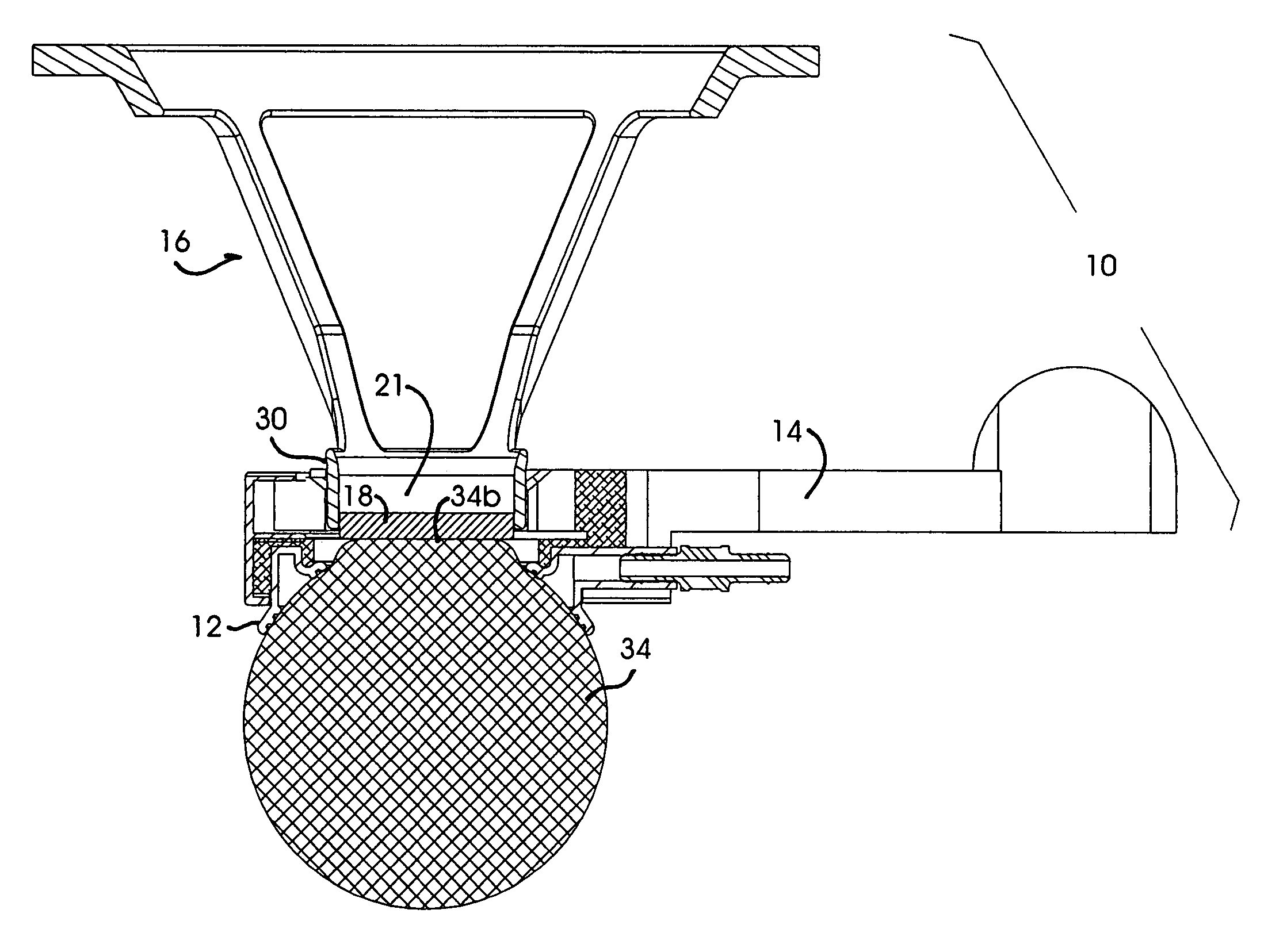
[0029]Conceptually, the present invention is directed to a mechanical apparatus that performs the functions of coupling the anterior surface of a target eye to a surgical laser and applanating said eye. The apparatus is termed mechanical because it directly couples the mechanical surface of an operative target, such as human corneal tissue, to a mechanical fixture of a surgical laser system, such as the distal tip of a laser beam's delivery system. Simply put, and in the context of a particular embodiment which will be described in greater detail below, the apparatus is affixed to the anterior surface of a human cornea and is affixed to the laser delivery system.

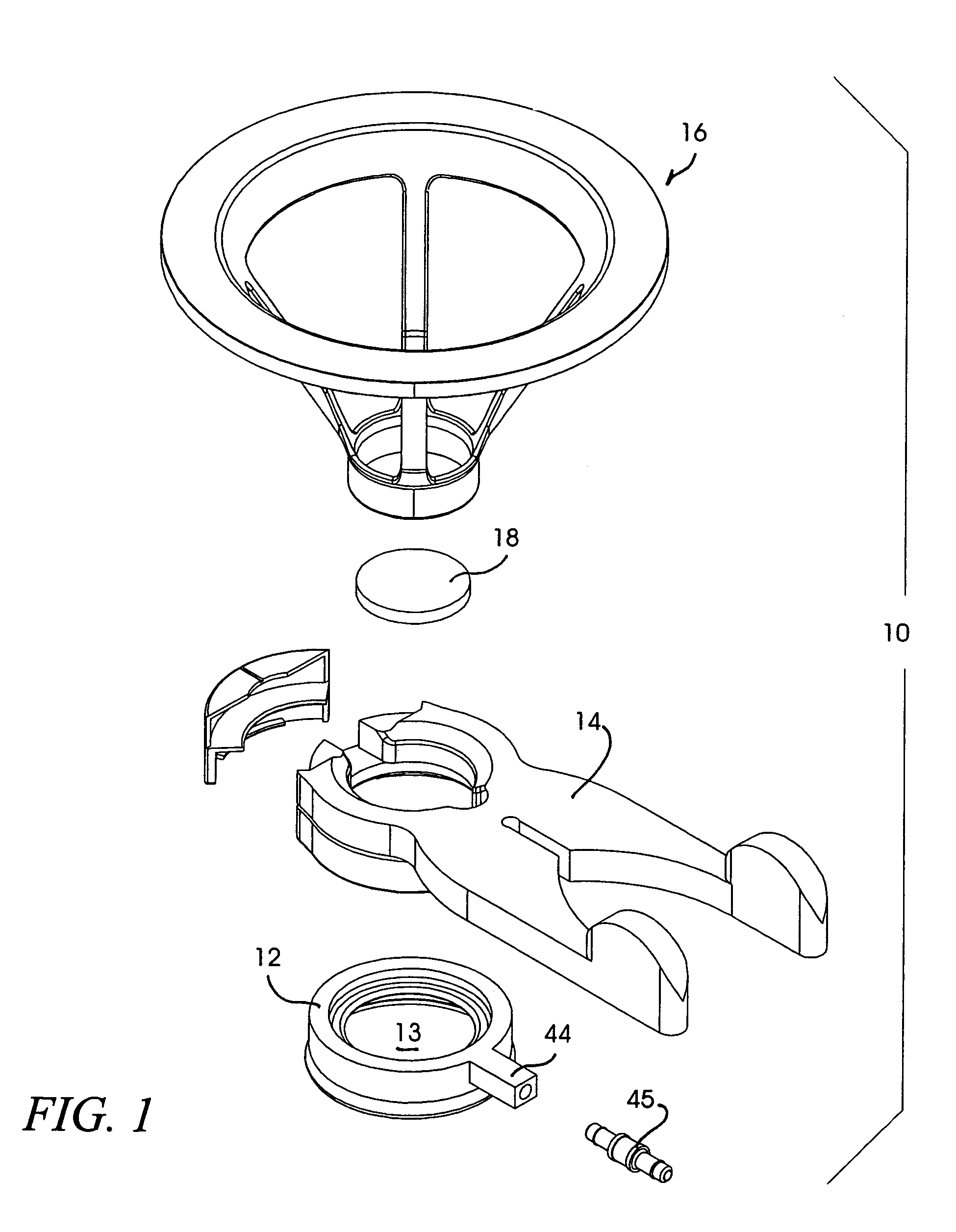
[0030]Referring initially to the exemplary embodiment of FIG. 1, an illustrative ocular fixation and applanation device is shown in an exploded, perspective view, and is generally indicated at 10. The ocular fixation and applanation device (referred to herein as simply an applanation device or alternatively, a patient interf...


PUM


Abstract

A method for applanating an anterior surface of a cornea and coupling the eye to a surgical laser is disclosed. A interface is provided which has a central orifice and top and bottom surfaces. A suction ring is removably coupled to the bottom surface of the interface. The interface is positioned over an operative area of an eye, such that the suction ring comes into proximate contact with the surface of the eye. A suction is applied to the suction ring to stabilize the position of the interface relative to the operative area of the eye. An applanation lens is positioned in proximate contact with the operative area of the eye. Finally, the applanation lens is coupled to the interface to stabilize the position of the lens relative to the operative area of the eye.

Description

CROSS REFERENCE TO RELATED APPLICATIONS[0001]The present application is related to U.S. patent applications Ser. No. 09 / 172,819, filed Oct. 15, 1998, now U.S. Pat. No. 6,254,595, and U.S. patent applications Ser. No. 09 / 266,453, filed Mar. 11, 1999, now U.S. Pat. No. 6,344,040, both of which are commonly owned by the assignee of the present application, the entire contents of which are expressly incorporated by reference. This application is a divisionsl application of U.S. patent application Ser. No. 09 / 772,539, filed Jan. 29, 2001, now U.S. Pat. No. 6,863,667, which is incorporoted by reference herein in its entirety.FIELD OF THE INVENTION[0002]The present invention relates to an interface device for ophthalmic laser surgery and, more particularly, an interface apparatus used to stabilize the eye of a patient with respect to a laser beam during ophthalmic surgery, and to reconfigure the cornea for precision laser interaction.BACKGROUND OF THE INVENTION[0003]In recent years, signif...

Claims


Application Information

Patent Timeline
Patent Type & Authority Patents(United States)
IPC IPC(8): A61B18/18A61B17/30A61F9/008A61F9/009A61F9/01
CPCA61F9/009A61B2017/306A61F2009/00846A61F9/008
Inventor WEBB, R. KYLEBROWNELL, MICHAEL F.HORVATH, CHRISTOPHERJUHASZ, TIBORKURTZ, RONALD M.NAGY, LASZLO I.ROSS, MARK W.SUAREZ, CARLOS G.
Owner AMO DEVMENT
Why Eureka
Try Eureka