Process device with quiescent current diagnostics

a technology of process devices and diagnostics, applied in the direction of program control, testing/monitoring control systems, instruments, etc., can solve the problems of not being able to predict the impending failure of a process device, and requiring the unexpected shutdown of the entire process

Active Publication Date: 2006-03-28
ROSEMOUNT INC
View PDF360 Cites 58 Cited by
  • Summary
  • Abstract
  • Description
  • Claims
  • Application Information

AI Technical Summary

Problems solved by technology

When a process device fails, it is often necessary to shut down the entire process so that the failed device can be repaired or replaced.
Typically, it is not possible to predict an impending failure of a process device prior to its occurrence.
Thus, when the process device does fail, it occurs unexpectedly, and may require the unexpected shut down of the entire process.

Method used


Image

  • Process device with quiescent current diagnostics
  • Process device with quiescent current diagnostics
  • Process device with quiescent current diagnostics

Examples


Embodiment Construction

[0011]The present invention provides a diagnostic technique for predicting a failure of a process device prior to the occurrence of the failure. With the present invention, quiescent current draw is monitored. Changes in the quiescent current draw are detected and used to predict an impending failure of the process device.

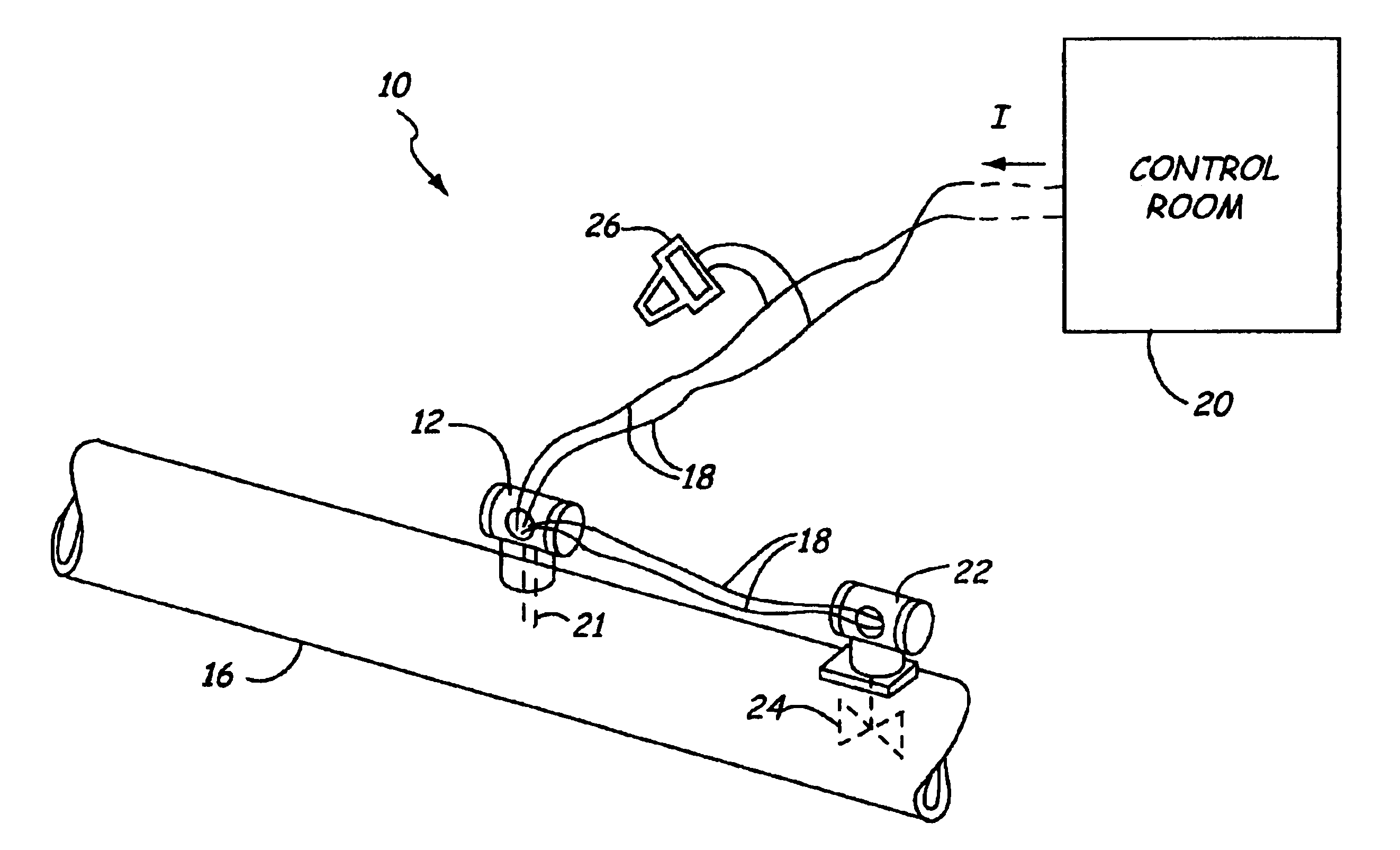
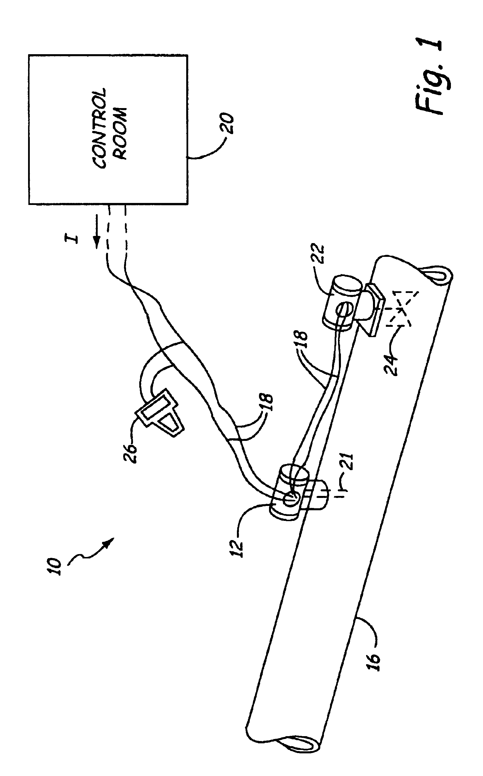
[0012]FIG. 1 is a diagram of process control system 10 which includes a transmitter 12 connected to process pipe 16. As discussed below, transmitter 12 is one type of process device and the present invention is applicable to any process device. Transmitter 12 is coupled to a two-wire process control loop which operates in accordance with the Fieldbus, Profibus or HART® standard. However, the invention is not limited to these standards or a two-wire configuration. Two-wire process control loop 18 runs between transmitter 12 and the control room 20. In an embodiment in which loop 18 operates in accordance with the HART® protocol. Loop 18 can carry a current I which i...


PUM

PropertyMeasurementUnit
quiescent currentaaaaaaaaaa
currentsaaaaaaaaaa
currentsaaaaaaaaaa

Abstract

A process device for use on an industrial process control system includes a quiescent current sensor configured to sense quiescent current draw of the process device. Diagnostic circuitry determines a diagnostic condition of the process device as a function of the sensed quiescent current.

Description

BACKGROUND OF THE INVENTION[0001]The present invention relates to process devices of the type used in industrial processes. More particularly, the present invention relates to diagnostics of such process devices.[0002]Field devices such as process controllers, monitors and transmitters, are used in the process control industry to remotely control or sense a process variable. For example, a process variable may be transmitted to a control room by a transmitter for use in controlling the process or for providing information about process operation to a controller. For example, information related to pressure of process fluid may be transmitted to a control room and used to control the process, such as oil refining.[0003]One typical prior art technique for transmitting information involves controlling the amount of power flowing through a process control loop. Current is supplied from a current source in the control room and the transmitter controls the current from its location in the...

Claims


Application Information

Patent Timeline
Patent Type & Authority Patents(United States)
IPC IPC(8): C12Q1/68G08B21/00H01T13/60G01R19/25G08C19/02
CPCG08C19/02G05B23/0283G01R19/2509G01R19/2506G05B23/0235G05B2219/33197Y02P90/80
Inventor HUISENGA, GARRIE D.LONGSDORF, RANDY J.
Owner ROSEMOUNT INC
Why Eureka
Try Eureka