Depression responsive switch unit

a switch unit and pressure-responsive technology, applied in the direction of switch side location, emergency actuators, snap-action arrangements, etc., can solve the problems of difficult task to achieve with a conventional two-step switch unit, second-step switch may be turned on inadvertently, and first-step switch has a relatively high on-load, so as to achieve the effect of reliable turning and increased useful li

Inactive Publication Date: 2006-03-28
JAPAN AVIATION ELECTRONICS IND LTD
View PDF13 Cites 80 Cited by
  • Summary
  • Abstract
  • Description
  • Claims
  • Application Information

AI Technical Summary

Benefits of technology

[0021]In the switch unit according to the second aspect of the present invention, the case comprises a rigid body, and even though there is no guide means for the knob, the retaining function of the resilient member is such that if the direction of depression deviates from the normal direction, and if one end of the knob is depressed, the switch can be reliably turned on. In addition, a return spring has an increased useful life and could be constructed in a compact manner.

Problems solved by technology

However, if an on-load is relatively high when an input is to be made to the first step switch, there is a likelihood that the second step switch may be turned on inadvertently.
Accordingly, the sheet itself has a high reaction, and thus there has been a disadvantage that the first step switch has a relatively high on-load.
However, such has been a difficult task to achieve with a conventional two-step switch unit.
This leads to problems that a clicking sensation is degraded, that a reversal may be prevented from occurring or that the useful life of the click plate 64 may be shortened.
However, if the reversal occurs as a result of a high load applied to the return spring which would occur during an edgewise depression, the return spring will be subject to correspondingly higher stresses, thus shortening the useful life.
A problem relating to the sensation of operation remains in a similar manner as in the arrangement of FIG. 23.

Method used


Image

  • Depression responsive switch unit
  • Depression responsive switch unit
  • Depression responsive switch unit

Examples


first embodiment

[0075]A first embodiment as a specific example of the first mode of carrying out the present invention will now be described. It should be understood that in the description to follow, corresponding parts which appear throughout the drawings are designated by like reference numerals in order to avoid a duplicated description as much as possible.

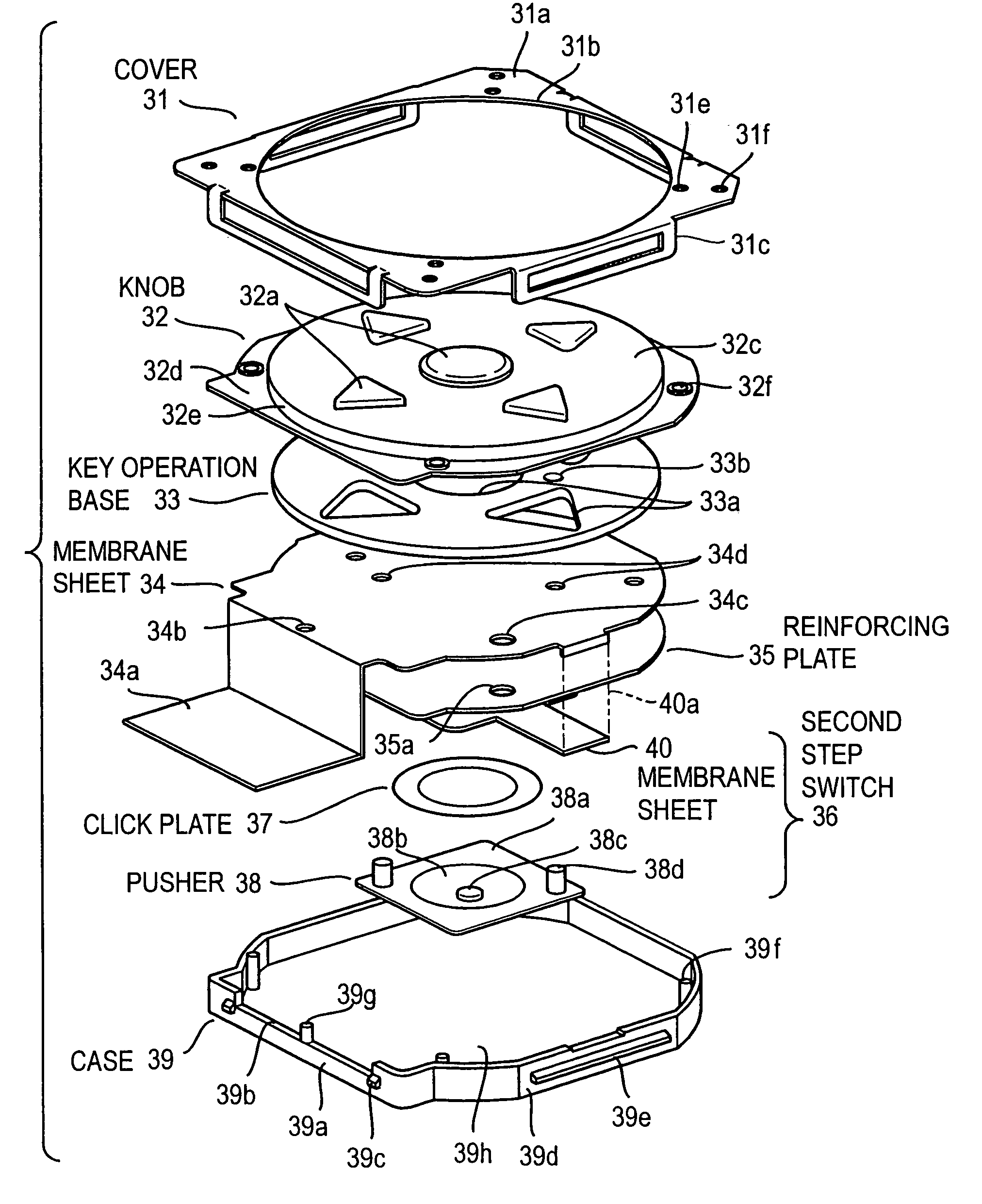
[0076]A cross section of the first embodiment taken along the line IV—IV shown in FIG. 5 is shown in FIG. 4, a plan view is shown in FIG. 5, and the exploded perspective view is shown in FIG. 6.

[0077]A cover (front plate) 31 comprises a metal sheet which is machined as required, and includes a square portion 31a in which a circular opening 31b is formed. Each side of the square portion 31a has a U-shaped detent 31c having short limbs which is bent in a direction perpendicular to the square portion 31a to extend toward the rear plate 39h.

[0078]A knob 32 comprises a square-shaped elastic sheet 32c, which extends outside the opening 31b formed ...

second embodiment

[0108]In the second embodiment, in order to reduce the number of parts, a sidewall 39a is molded integrally with a knob 32 as shown in FIG. 10, and the marginal portion 32d of the elastic sheet 32c (knob 32) is secured to the end face of the sidewall 39a along the full perimeter as by an integral molding. A redundant portion 32h which is U-shaped in section is formed in the marginal portion 32d of the elastic sheet 32c (knob 32) to extend along the inner periphery of the sidewall 39a. This facilitates an elastic deformation of the marginal portion 32d in a direction toward the rear plate and also makes an elastic deformation in a direction parallel to the rear plate more difficult to occur. In other words, the knob 32, the key operation base 33 and the reinforcing plate 35 are readily displaceable in the direction of a normal depression and are hardly displaceable in a direction perpendicular to the direction of a normal depression. Accordingly, if the knob 32 is edgewise depressed,...

third embodiment

[0112]The third embodiment is shown in FIGS. 11 to 16. In the third embodiment, instead of the cover 31 shown in the first embodiment, a case 39 is formed with a surface plate 39j in an integral manner with its sidewall, and a large circular opening 39k is formed in the surface plate 39j. A key operation base 33 is disposed to substantially block the opening 39k, and the key operation base 33 is formed with a depression opening 33c in a manner corresponding to each depressing piece 32a. In the present example, there are nine depression openings 33c as shown in FIG. 12, one being disposed at the center while the remaining eight openings are disposed on a common circle at an equal interval.

[0113]As mentioned previously, in the present example, the depressing piece 32a and the small projection 32b are integrally molded with a hard resin, and this is adhesively secured to or integrally molded with the elastic sheet 32c which comprises a thermoplastic elastomer 32. Each depressing piece ...


PUM


Abstract

A pusher formed of a rubber material, a click plate, a membrane switch which serves as a second step switch, a reinforcing plate, a membrane sheet on which a plurality of first step switches are formed, a key operation base and a knob are sequentially assembled into a case. The knob includes a plurality of depressing pieces having on its internal surface a projection which moves into contact with each membrane switch and also includes a marginal portion which is supported by the top surface of the case. The knob is thin-walled except for the depressing piece, and the thin-walled portion comprises a thermoplastic elastomer or silicone rubber. The knob, the key operation base and the reinforcing plate are secured together. As the depressing piece is depressed, the thin-walled portion which is located therearound becomes flexed, whereby the membrane switch is depressed by the projection to turn the switch on. When the depressing piece is further depressed, the reinforcing plate moves and the click plate reverses, turning the switch on.

Description

BACKGROUND OF THE INVENTION[0001]The present invention relates to a depression responsive switch unit which is turned on in response to the depression of a knob.[0002]A conventional depression responsive two-step switch unit which is disclosed in Japanese Laid-Open Patent Application No. 315,682 / 96 (laid open Nov. 29, 1996) will be briefly described with reference to FIGS. 1, 2, 3A and 3B. A rectangular case 2 includes a surface plate 2a, in which a rectangular opening 2-1 is formed, and a key top 3 is disposed to substantially block the opening 2-1. The key top 3 includes an elongate frame-shaped sidewall 3g, on the inner surface of which a reinforcing plate 3c is fitted and is secured in position by claws 3d. A membrane sheet 6 is held in overlapping relationship with the front side of the reinforcing plate 3c, and a surface sheet 3e is disposed on the front side of the membrane sheet 6 and is adhesively bonded to the end face of the sidewall 3g of the key top 3.[0003]A plurality ...

Claims


Application Information

Patent Timeline
Patent Type & Authority Patents(United States)
IPC IPC(8): H01H9/00H01H5/30H01H13/66H01H13/14H01H13/48H01H13/52H01H13/702H01H13/712H01H13/807H01H25/04
CPCH01H13/702H01H13/807H01H25/041H01H2235/00H01H2225/002H01H2225/018H01H2221/058
Inventor MATSUMOTO, TADANAOIWAO, NAOKI
Owner JAPAN AVIATION ELECTRONICS IND LTD
Why Eureka
Try Eureka