Method for recognizing an obstructive situation in a motor driven element

a technology of obstructive situations and motors, which is applied in the direction of motor/generator/converter stoppers, dynamo-electric converter control, instruments, etc., can solve problems such as obstructive situations, and achieve the effect of much greater accuracy

Inactive Publication Date: 2006-03-28
LEOPOLD KOSTAL GMBH & CO KG
View PDF11 Cites 5 Cited by
  • Summary
  • Abstract
  • Description
  • Claims
  • Application Information

AI Technical Summary

Benefits of technology

[0011]In the method in accordance with the present invention, the system concludes that an obstructed situation is present when the values determined at the immediately preceding detection time points exhibit a change behavior with respect to one another over time that falls in a range of values of the observed variable that is typical for the obstructed situation to be recognized and that extends over several values. Thus, the method includes a sample comparison which involves recognizing the occurrence of an obstructed situation not on the basis of a threshold, but rather on the basis of the typical change behavior of the values determined when such an obstructed situation occurs. Such a sample comparison is able to recognize the actual presence of an obstructed situation with much greater accuracy.

Problems solved by technology

Such obstructive situations occur, for example, when something is being pinched.
However, if the recognition method has its cut-off value set too high, then it recognizes a case of pinching at a relatively late point in time.

Method used


Image

  • Method for recognizing an obstructive situation in a motor driven element
  • Method for recognizing an obstructive situation in a motor driven element
  • Method for recognizing an obstructive situation in a motor driven element

Examples


Embodiment Construction

)

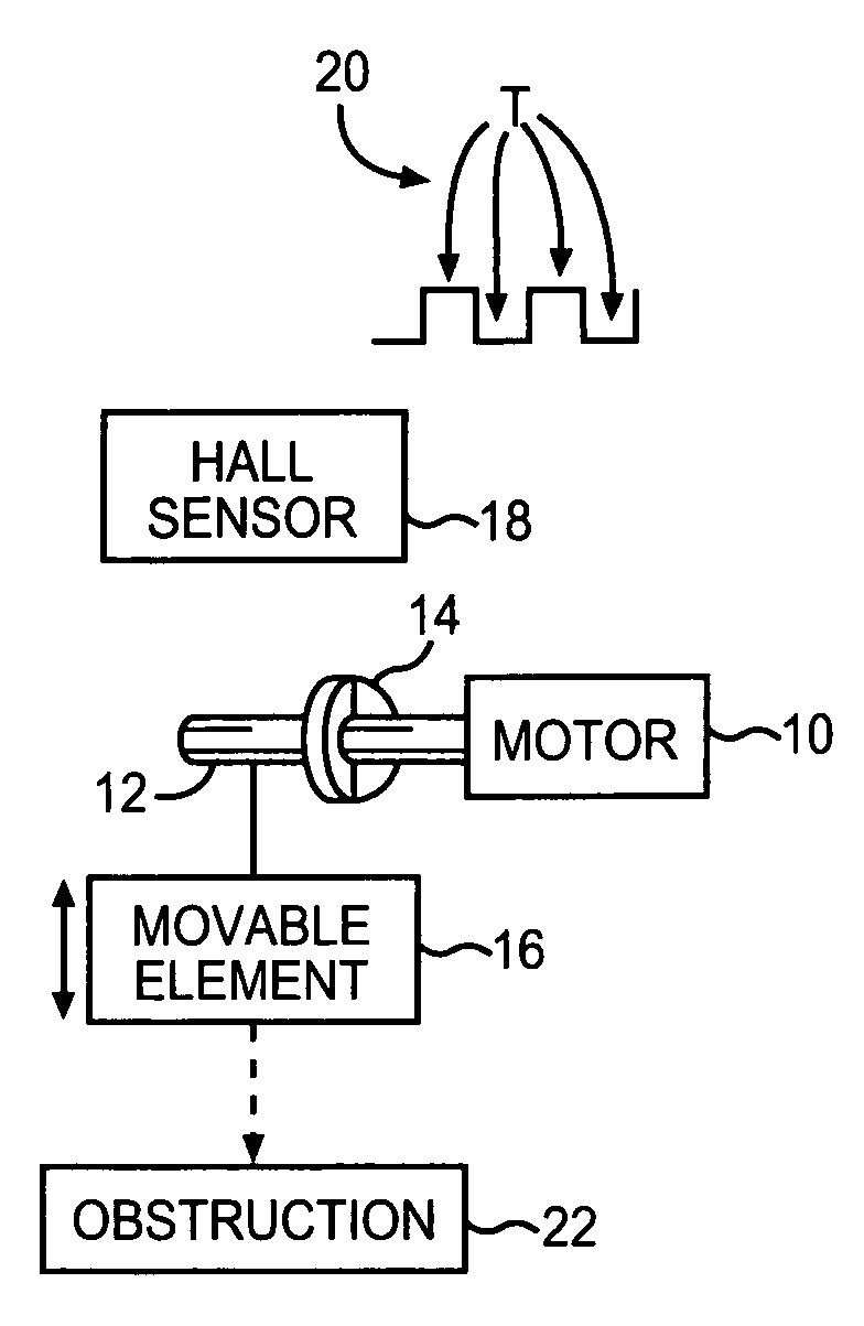
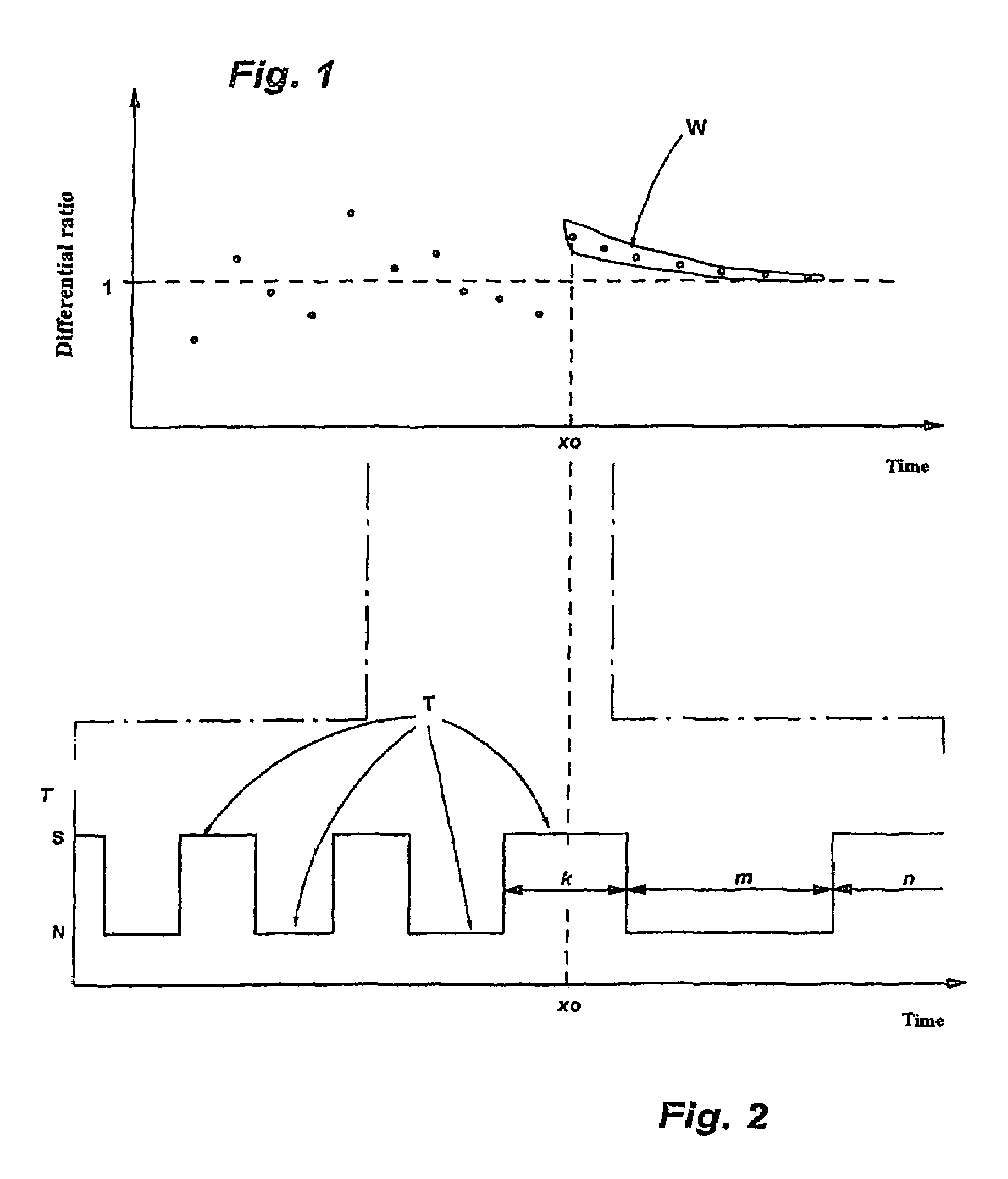
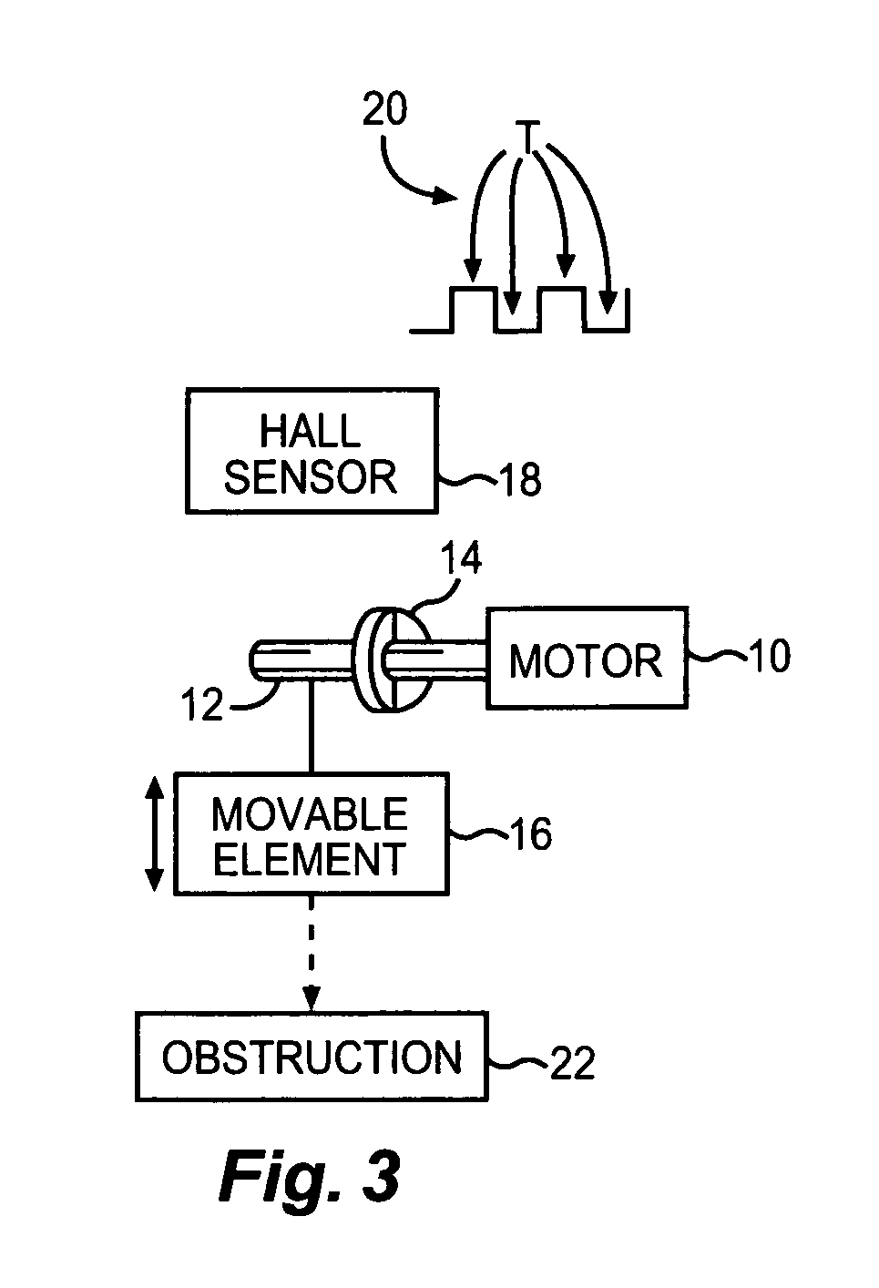
[0020]The shaft 12 of an electric window raising motor 10 in a motor vehicle has arranged on it a magnet 14 having four poles in the peripheral direction. A Hall sensor arrangement 18 that is stationary to this magnet is used for detection of the respective magnet polarity that is applied to the Hall sensor. Thus, in this sample embodiment shown, rotation of the armature shaft by 360° is characterized by passing through four periods 20, referred to as motor periods T. Thus, the length of a motor period is a direct measure of the rotational speed of the window raising motor.

[0021]When the window 16 driven by the window raising motor is closed under normal conditions the window raising motor ideally rotates at a constant speed. In reality, however, this is subject to statistically distributed fluctuations. These fluctuations are not constant and are the result of the power transmission system and the friction of the window in its guide. Operation of the drive motor with constant rota...


PUM


Abstract

A method for recognizing an obstructed situation of a traveling element. The method includes evaluating a variable containing information about the motor's rotational speed as the motor is driving the element. Starting from a current detection time point, the sequence of values of the variable determined at immediately preceding detection time points are observed. Change in behavior of the sequence of observed values of the variable with respect to one another over time are then compared with a value range of the variable that is indicative of the element being obstructed. A sufficient match between the value range of the variable and the sequence of observed values of the variable exists if at least three successive observed values of the variable fall within the variable value range. The element is determined to be obstructed upon the existence of a sufficient match. The variable includes the duration of motor time periods.

Description

CROSS-REFERENCE TO RELATED APPLICATIONS[0001]This is a continuation of International Application PCT / EP03 / 01643, published in German, with an international filing date of Feb. 19, 2003, and which claims priority to DE 102 07 234.5 filed Feb. 21, 2002.BACKGROUND OF THE INVENTION[0002]1. Field of the Invention[0003]The present invention relates to a method for recognizing an obstructed situation of a motor-driven traveling element by evaluating a variable containing information about the rotational speed of the motor.[0004]2. Background Art[0005]Methods are used to detect obstructive situations of a motor-driven element such as an electric motor-driven element. Such obstructive situations occur, for example, when something is being pinched. Such methods are used, for example, to operate a window raising motor which closes a window in a motor vehicle. The methods are intended to ensure that objects, especially parts of a person's body, are not pinched in the closing window gap when the...

Claims


Application Information

Patent Timeline
Patent Type & Authority Patents(United States)
IPC IPC(8): H02P7/00H02H7/085
CPCH02H7/0851
Inventor KONIGSHAUS, MARKUS
Owner LEOPOLD KOSTAL GMBH & CO KG
Why Eureka
Try Eureka