
Method and circuit for adjusting a reference voltage signal

Active Publication Date: 2006-03-28
MONTEREY RES LLC
View PDF11 Cites 40 Cited by
  • Summary
  • Abstract
  • Description
  • Claims
  • Application Information

AI Technical Summary

Benefits of technology

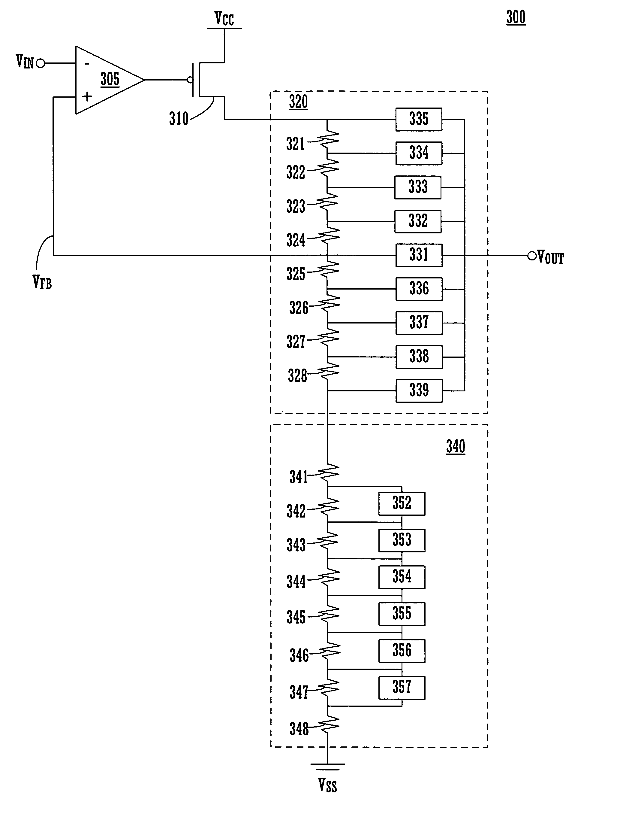
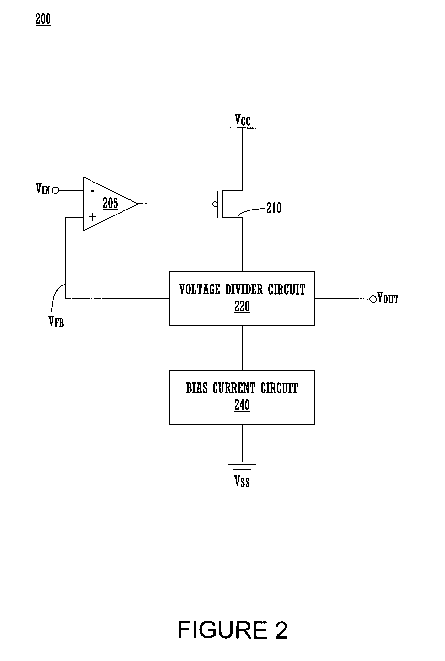
[0008]Advantageously, embodiments of the present invention maintain a substantially constant DC operating point of the transistor. Embodiments of the present invention also maintain a substantially constant feedback path to the operational amplifier. The substantially constant DC operating point of the transistor and the substantially constant feedback path to the operational amplifier improve the stability of the voltage trim circuit over all trim voltages.

Problems solved by technology

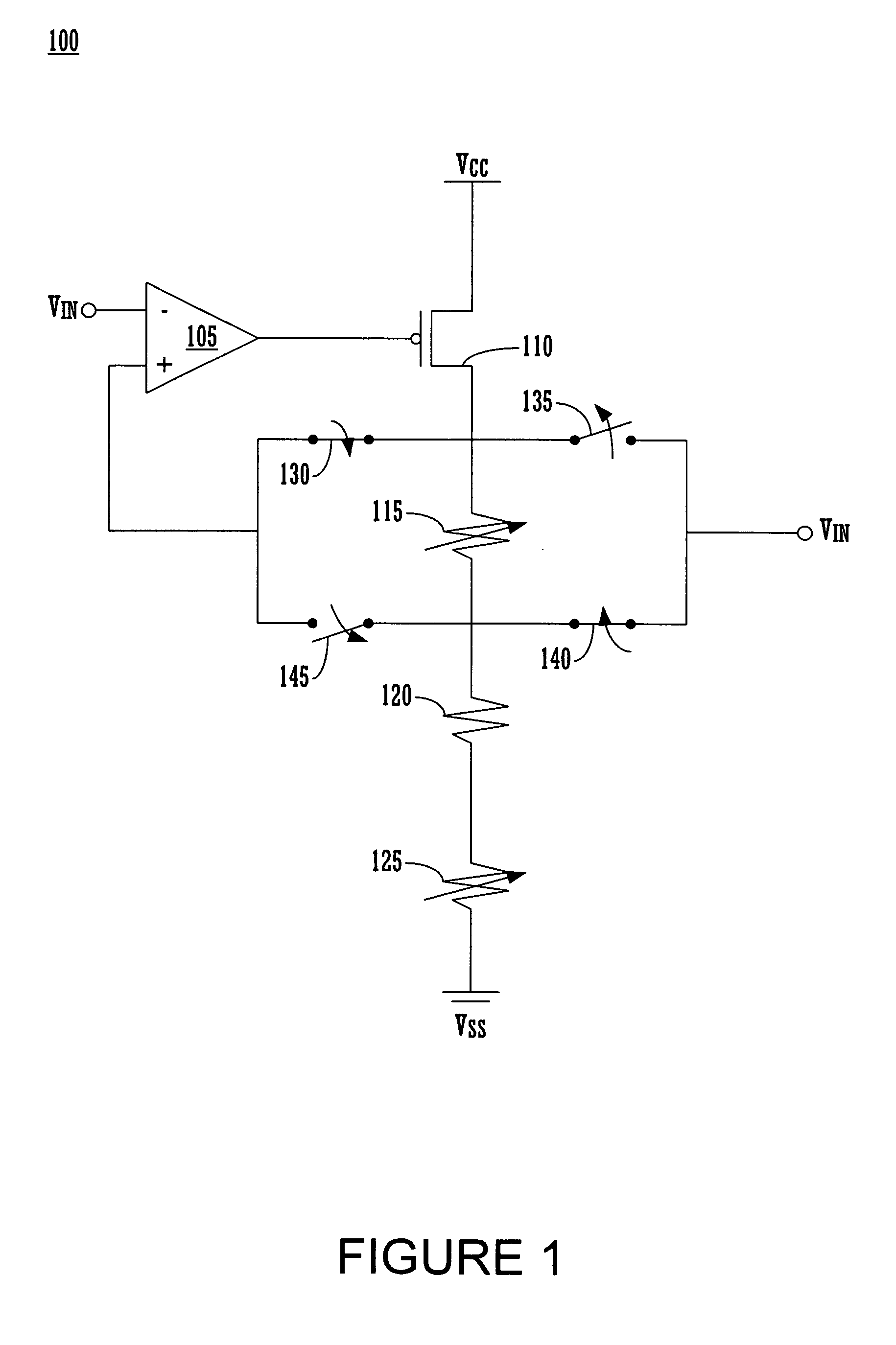
However, the conventional voltage trim circuits may exhibit instability.

Method used


Image

  • Method and circuit for adjusting a reference voltage signal
  • Method and circuit for adjusting a reference voltage signal
  • Method and circuit for adjusting a reference voltage signal

Examples


Embodiment Construction

[0015]Reference will now be made in detail to the embodiments of the invention, examples of which are illustrated in the accompanying drawings. While the invention will be described in conjunction with these embodiments, it will be understood that they are not intended to limit the invention to these embodiments. On the contrary, the invention is intended to cover alternatives, modifications and equivalents, which may be included within the spirit and scope of the invention as defined by the appended claims. Furthermore, in the following detailed description of the present invention, numerous specific details are set forth in order to provide a thorough understanding of the present invention. However, it is understood that the present invention may be practiced without these specific details. In other instances, well-known methods, procedures, components, and circuits have not been described in detail as not to unnecessarily obscure aspects of the present invention.

[0016]Referring t...


PUM


Abstract

A voltage trim circuit, in accordance with one embodiment of the invention, includes an operational amplifier, a transistor, a voltage divider and a bias current circuit. The operational amplifier is coupled to an input. The transistor is coupled to the operational amplifier and a first potential. The voltage divider circuit is coupled to the operational amplifier, the transistor and an output. The bias current circuit is coupled to the voltage divider circuit and a second potential. The voltage divider generates an output voltage as a function of a selectable divider ratio and provides a substantially constant feedback path to the operational amplifier. The bias current circuit provides for selectively adjusting a load resistance of the transistor to maintain a substantially constant load current through the transistor.

Description

CROSS-REFERENCE TO RELATED APPLICATION[0001]This application claims the benefit of U.S. Provisional Application No. 60 / 457,799 filed Mar. 25, 2003 entitled “Method and Apparatus for Adjusting a Reference Voltage”, by Wilson et al. The provisional application is incorporated herein by reference in its entirety.BACKGROUND OF THE INVENTION[0002]In the conventional art, circuit operation in integrated circuits often depends upon one or more accurate and stable voltage references. For example, numerous analog circuits, such as amplifiers, current mirrors and the like depend upon current sources that conduct stable currents. The accuracy and stability of the current sources typically depend upon the accuracy and stability of one or more reference voltages applied to the gates of transistors that provide the current sources. Other circuits, particularly those that control the switching response of digital circuits depend upon the accuracy and stability of the reference voltages to control ...

Claims


Application Information

Patent Timeline
IPC IPC(8): G05F1/10G05F3/02
CPCG05F1/56
Inventor WILSON, ADAM B.JURASEK, RYAN
Owner MONTEREY RES LLC
Learn More