Arrangement of card slot in laptop computer

a card slot and laptop computer technology, applied in the field of notebook computers, can solve the problems of obstructive attached cables, complicated and expensive fixation, and difficult to fix cameras, and achieve the effect of improving signal transmission efficiency and facilitating image a person

Inactive Publication Date: 2006-03-28
FUJIFILM CORP
View PDF16 Cites 13 Cited by
  • Summary
  • Abstract
  • Description
  • Claims
  • Application Information

AI Technical Summary

Benefits of technology

[0010]Particularly, a wireless communication device, which transmits and receives signals in a predetermined method using radio waves or light, can be arranged at a higher position than the base unit of the personal computer, and this improves the signal transmission efficiency. Moreover, the image pickup part can be arranged at a higher position than in the conventional laptop computer, it is easier to image a person who is operating the personal computer.

Problems solved by technology

This is, however, complicated and requires much cost.
On the other hand, Japanese Provisional Publication No. 8-153175 proposed a camera card to be inserted into the PC card slot, but if such a PC card type camera is used for the conventional laptop computer, it is difficult to fix the camera and the attached cable is obstructive.
In this case, the image pickup part 96 is shadowed by the hand of the operator, and this is very inconvenient.

Method used


Image

  • Arrangement of card slot in laptop computer
  • Arrangement of card slot in laptop computer
  • Arrangement of card slot in laptop computer

Examples


first embodiment

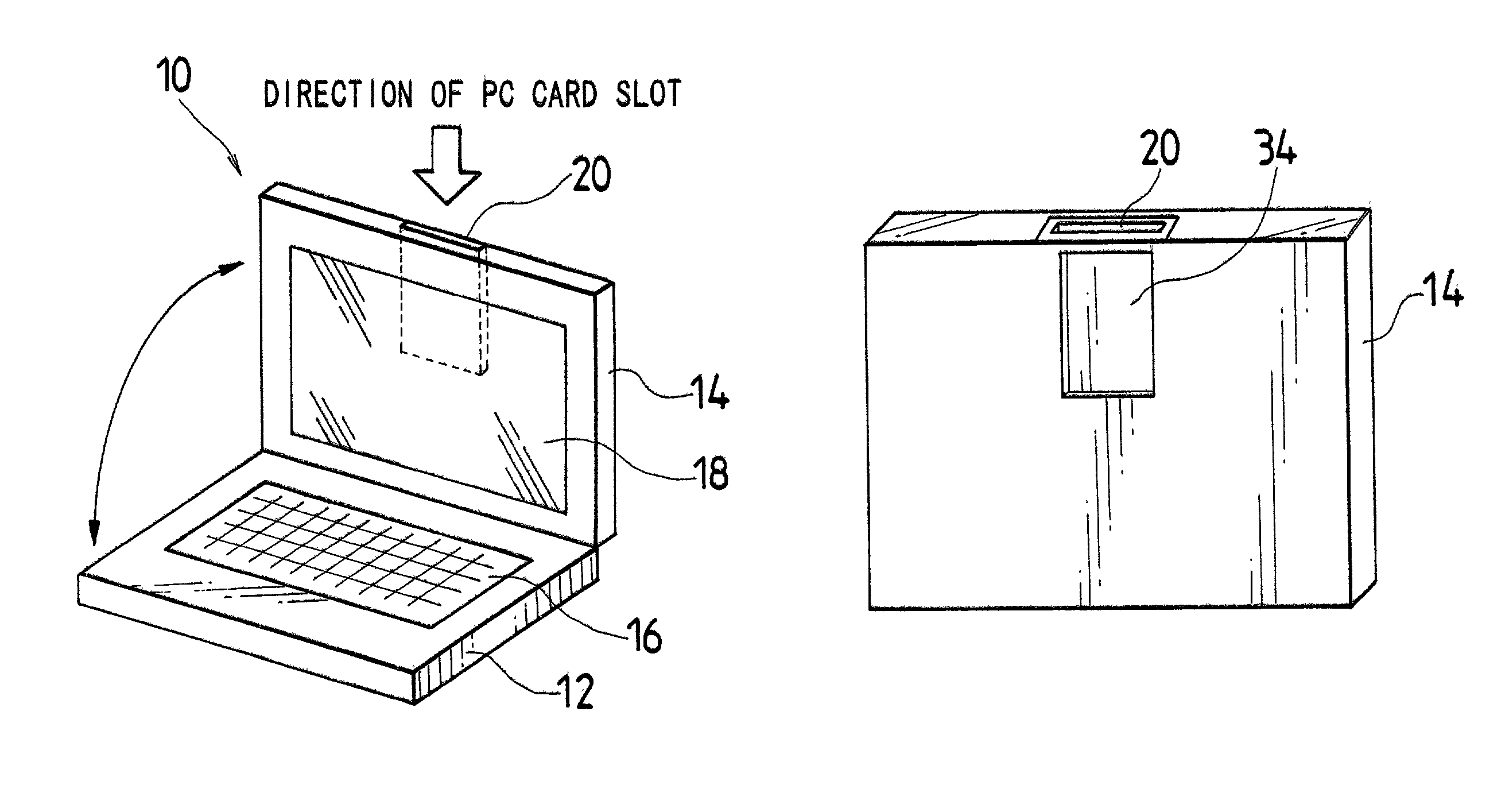
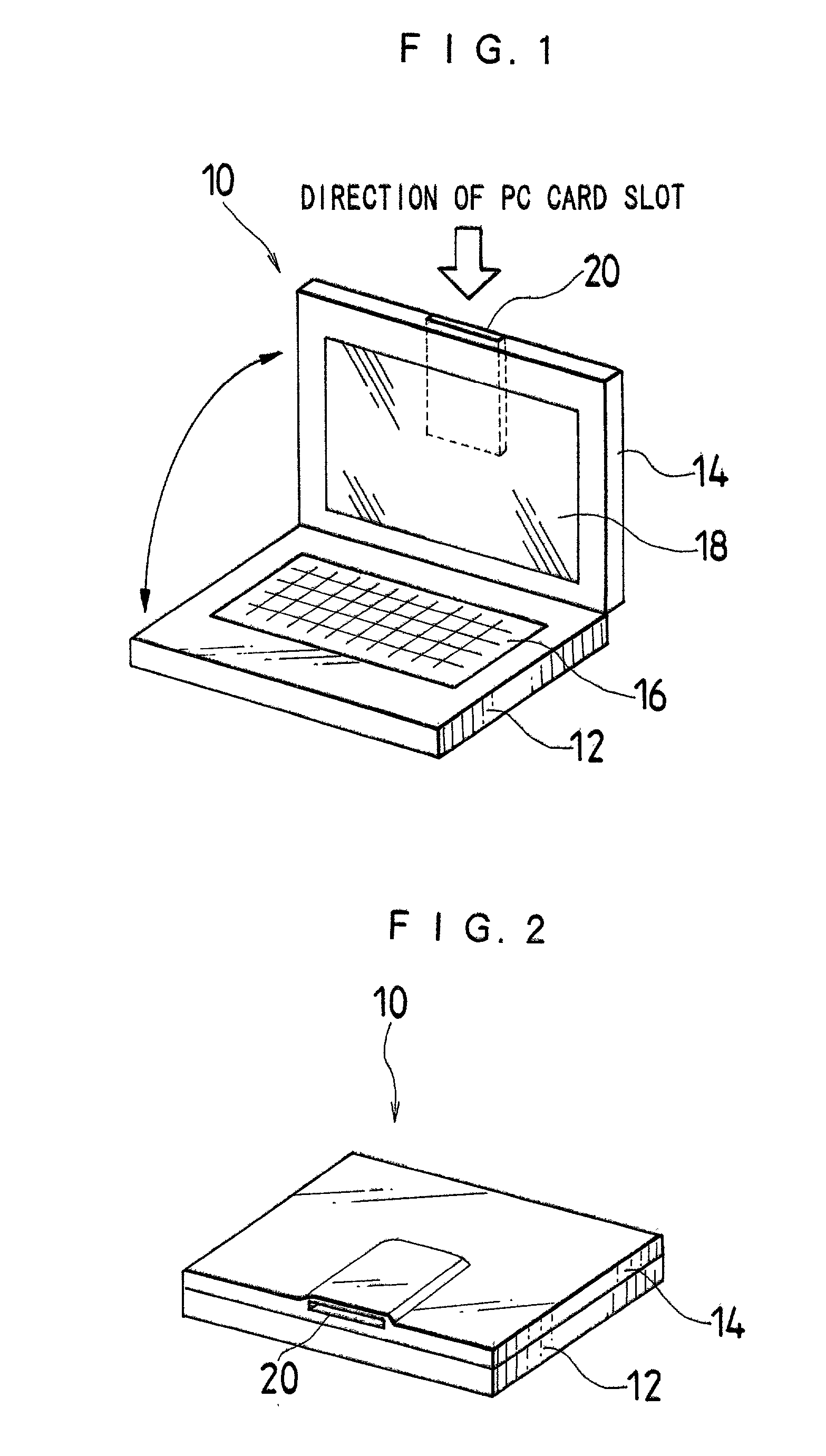
[0025]FIGS. 1 and 2 are perspective views showing a laptop computer 10 according to the present invention. FIG. 1 shows the laptop computer 10 that is being in use, and FIG. 2 shows the laptop computer 10 in not use or a closed state. As shown in FIGS. 1 and 2, the laptop computer 10 comprises a base unit 12 and a display unit 14, which is connected to the base unit 12 through a connection part such as a hinge mechanism (not shown).

[0026]The base unit 12 contains a memory, a hard disk, a central processing unit (CPU), and the like (not shown). An input part or a keyboard 16 is provided at the top part of the base unit 12. An input device such as a trackpad, a trackball and a joystick may be provided in addition to or instead of the keyboard 16.

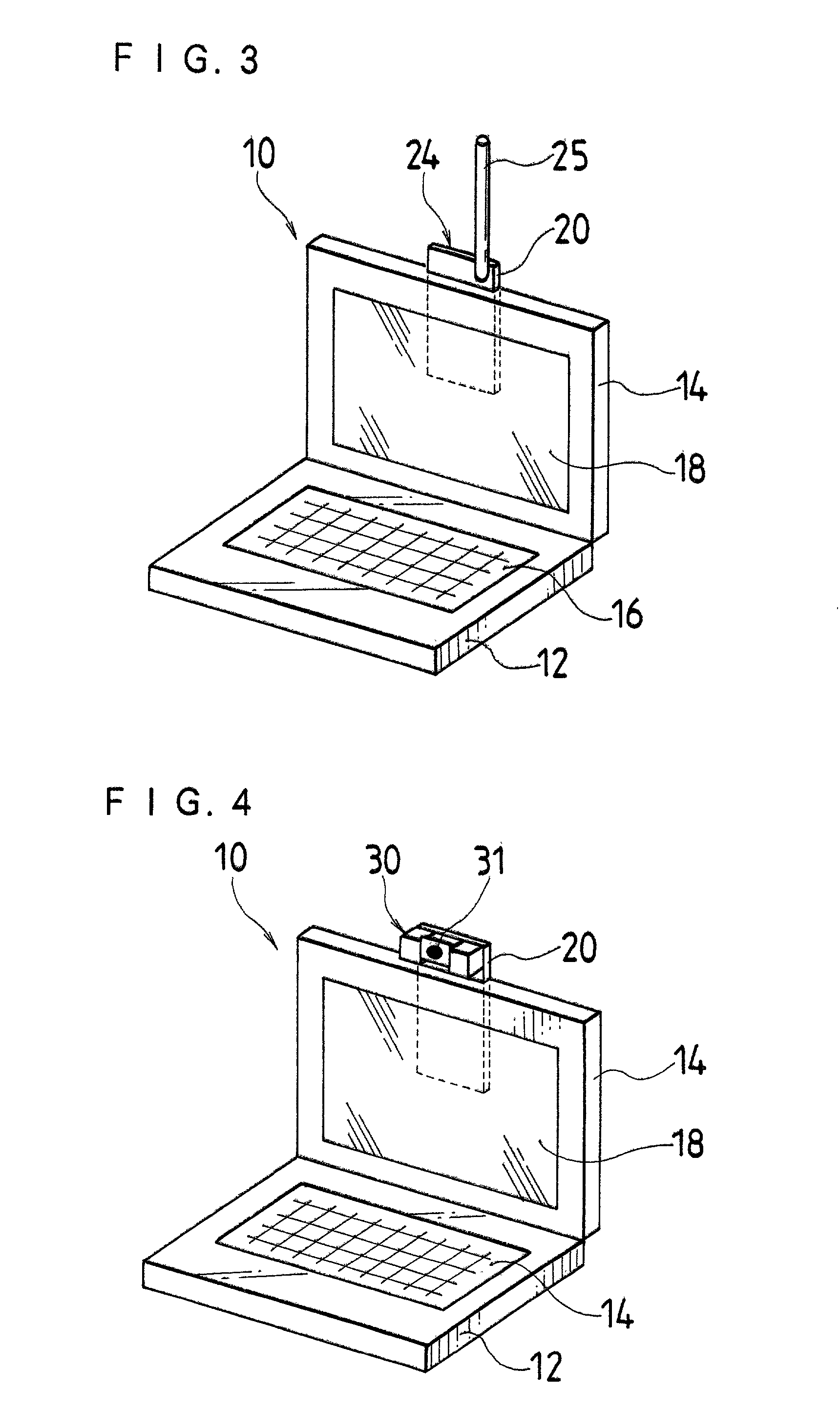
[0027]A flat display 18 such as a liquid crystal display (LCD) is incorporated in the display unit 14. When the laptop computer 10 is in use, the display unit 14 is opened so that the face of the flat display 18 forms a desirable angle, which ...

second embodiment

[0035]For example, if the display 18 is smaller than the display unit 14 as in the second embodiment in FIG. 5, the PC card slot 20 may be arranged at the right side (or the left side) of the display 18 in order to prevent the PC card slot 20 and the display 18 from overlapping. This reduces the thickness of the display unit 14, and eliminates the unevenness of the outer surface of the display unit 14 shown in FIG. 2.

[0036]Although the PC card slot 20 may be arranged at either right or left of the display 18, it is preferable to provide the PC card slot 20 at the right side of the display 18 as shown in FIG. 5 since the majority of operators are right-handed.

third embodiment

[0037]FIG. 6 shows the present invention. As shown in FIG. 6, the PC card slot 20 may be provided at the right side (or the left side) of the display unit 14 so that the cards (not shown in FIG. 6) can be inserted from the right side (or the left side) of the display 18. Of course, it is possible to provide the PC card slot 20 at an arbitrary height at either the right or left side of the display unit 14.

[0038]Although not illustrated in the drawing, if the display 18 is relatively small as described with reference to FIG. 5, the PC card slot 20 is arranged at the lateral side of the display unit 14 in such a manner that the PC card slot 20 and the display 18 do not overlap each other. This reduces the thickness of the display unit 14.

[0039]It is preferable to provide a cutout part or an opening 34 in the reverse side of the display 18 as shown in FIG. 7. Whether the card is inserted or not and which type of the card is currently used can be checked through the opening 34. A transpa...


PUM


Abstract

A display unit containing a display is openably attached to a base unit of a laptop computer. While the laptop computer is not in use, the display unit is closed over the top face of the base unit with a display face of the display being inward. To use the laptop computer, the display unit is opened to form a desirable angle with the operation face of an input part on the base unit. A PC card slot is formed in the display unit, and a card can be mounted at a position away from a keyboard. Therefore, the card inserted into the PC card slot does not obstruct the operation of the input part. Particularly, if the PC card slot is arranged above at the top of the display, the signal transmission in the wireless communication using a wireless communication card can be performed efficiently and an operator of the personal computer can easily take a picture by a PC card camera.

Description

BACKGROUND OF THE INVENTION[0001]1. Field of the Invention[0002]The present invention relates generally to notebook or laptop computers, and more particularly to the arrangement of a card slot, which accepts compatible cards for enhancing the computer's functions.[0003]2. Description of Related Art[0004]Shown in FIG. 8 is a conventional laptop computer 80. A display unit 84 is openably attached to a base unit 82 through a connection part 85. A keyboard 86 as an input device is provided at the top part of the base unit 82, and a display 88 is contained in the display unit 84. Such a laptop computer normally has a PC card slot 90 confirming the Personal Computer Memory Card International Association (PCMCIA) standard arranged at the side of the base unit 82. The PC card slot 90 is an externally accessible expansion slot to accept a compatible card or a PC card (a small, removable, externally accessible circuit board housing a device such as a modem or disk drive) for enhancing the com...

Claims


Application Information

Patent Timeline
Patent Type & Authority Patents(United States)
IPC IPC(8): H05K5/02G06F1/16
CPCG06F1/1616G06F1/1656G06F1/1637
Inventor MISAWA, TAKESHI
Owner FUJIFILM CORP
Why Eureka
Try Eureka