
Rock fragmentation analysis system

a fragmentation analysis and rock technology, applied in the field of fragmentation analysis, can solve the problems of only being able to analyze one image at a time, and fragmentation software packages are only able to produce fragmentation distribution, and achieve the effect of distributing the processing load of the image processing system

Active Publication Date: 2006-03-28
INCO
View PDF21 Cites 104 Cited by
  • Summary
  • Abstract
  • Description
  • Claims
  • Application Information

AI Technical Summary

Benefits of technology

[0008]The rock fragmentation analysis system is designed to operate on-line, i.e., while the mine, quarry, etc. is fully functional. Preferably, the two or more processors provided within the image processing system distribute the processing load of the image processing system.

Problems solved by technology

Further, commercially available fragmentation software packages are only able to produce fragmentation distribution curves from single digital, print photographs, 35-mm slides or videotapes.
A major drawback of these available software packages is that they can only analyze one image at a time.

Method used


Image

  • Rock fragmentation analysis system
  • Rock fragmentation analysis system
  • Rock fragmentation analysis system

Examples


case b

[0150]5. Begin a for-loop by varying the threshold from Mean minus Sigma minus 15 to Mean+Sigma+15 in steps of 5.[0151]5.1 Obtain a binary image of the bucket intensity image using the threshold step.[0152]5.2 Mask-out the area outside the ROI.[0153]5.3 Fill the dark patches having a size smaller than shadowsize1 (default is 60). Then, darken an area corresponding to the shadow area in the bucket intensity image and call it Binarized_Image1.[0154]5.4 Fill the dark patches having a feret diameter smaller than shadowsize2 (default is 20). Then, darken an area corresponding to the shadow area in the bucket intensity image and call it Binarized_Image2.[0155]5.5 Create three different watershed lines for three cases as follows:[0156]Case a: Binarized_Image1 and set the minimum variation of the watershed to 2. Overlay the watershed lines on Binarized_Image1 and call it Blob1.[0157] Use Binarized_Image1 and set the minimum variation of the watershed to 1. Overlay the watershed lines and Bi...


PUM


Abstract

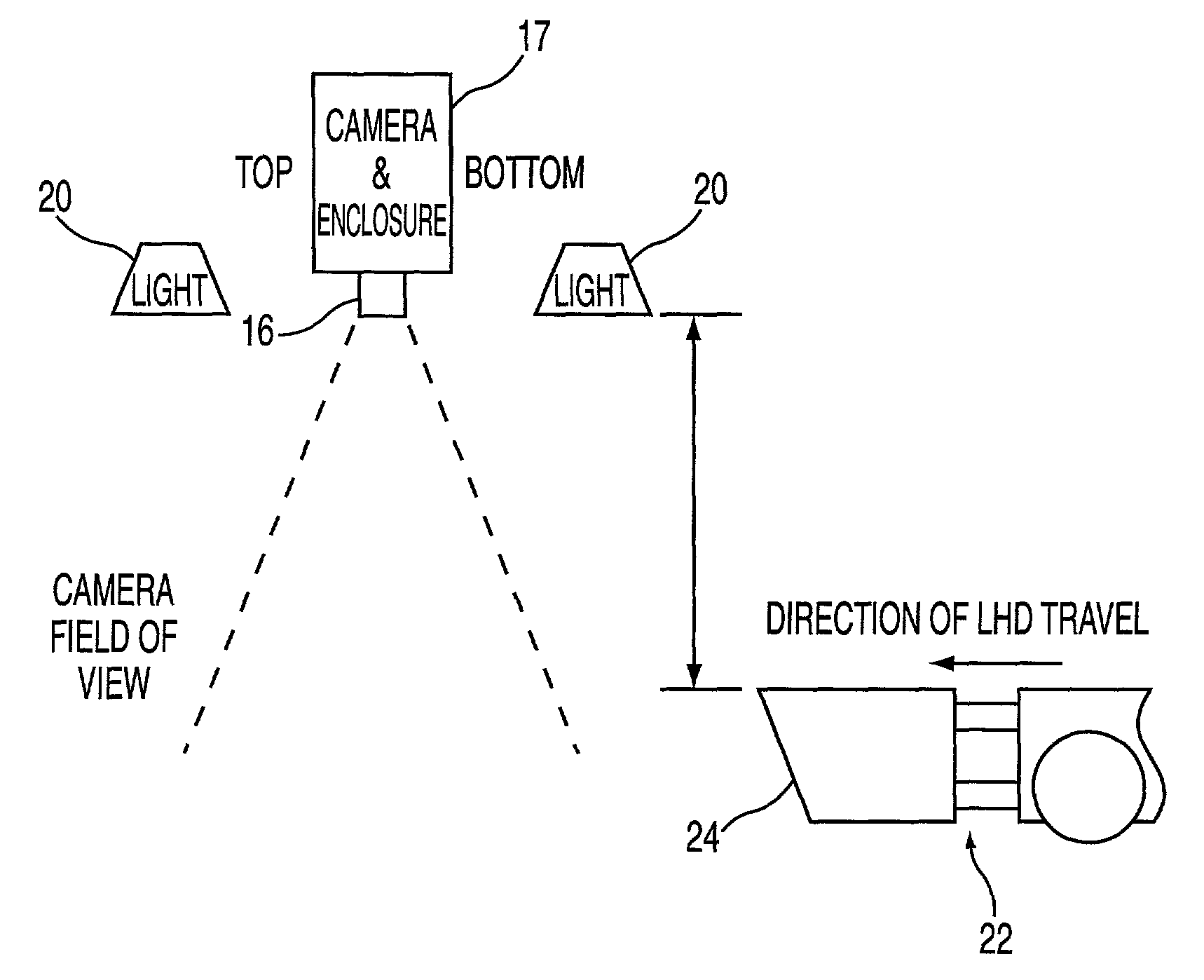
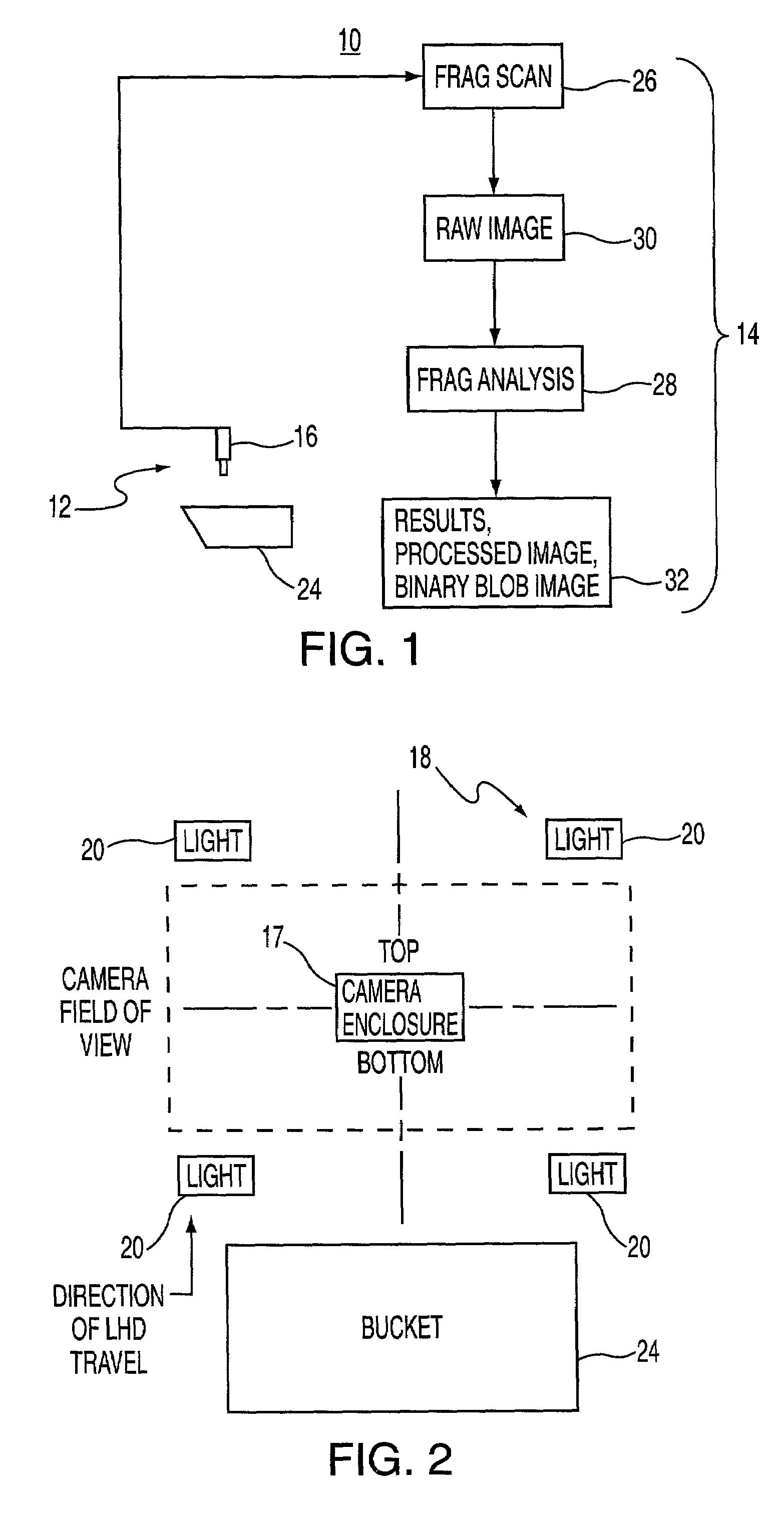
A rock fragmentation analysis system is provided for analyzing blasted rock (or other fragmented particles) to assess quality of a blast for efficient processing of subsequent operations in a mine, a quarry, etc. The system includes a hardware system and an image processing system. The hardware system includes a camera and a lighting system. The lighting system illuminates an area of the mine, quarry, etc. where a load haul dump (LHD) vehicle passes through. Once the LHD vehicle passes through the illuminated area, the camera provides video signals of scoop-top view images of the LHD vehicle to the image processing system via known communication means, such as hard-wired and wireless. The image processing system receives the video signals, captures the scoop-top view images, evaluates the images for subsequent fragmentation analysis, and performs the rock fragmentation analysis. The image processing system performs these functions using several software modules. Two such software modules are the Fragmentation Scanning (FragScan™) and the Fragmentation Analysis (FragAnalysis™) software modules. The FragScan software module scans the video signals until it captures a valid image for analysis by the FragAnalysis software module. Once the FragScan triggers on the image, a raw image and other details corresponding to the captured image are buffered for subsequent rock fragmentation analysis by the FragAnalysis software module. The rock fragmentation analysis is designed to estimate the major diameter of each rock visible in the image. The overall size distribution of the rocks in the image is output by the FragAnalysis software module, and the corresponding input image and the binary blob image, i.e., the processed image, are stored by the image processing system.

Description

TECHNICAL FIELD[0001]The instant invention relates to fragmentation analysis in general and, more particularly, to a rock fragmentation analysis system for analyzing blasted rock.BACKGROUND ART[0002]Fragmentation analysis of blasted rock is an important process control activity, particularly in underground mining, for optimizing productivity and cost. Fragmentation analysis includes the estimation of mean particle size and the size distribution related to percent passing in a sieve analysis. With the advancement of camera and imaging technology, the use of photographic based image analysis systems has become a convenient and better alternative to traditional sieving of rock blasts. As a result, mining industries have recently taken an initiative to implement automated image analysis systems for rock fragmentation analysis.[0003]An automated image analysis system has the capacity to monitor the blasted material quality continuously as opposed to only sampling data analysis as in the ...

Claims


Application Information

Patent Timeline
Patent Type & Authority Patents(United States)
IPC IPC(8): G06K9/00G06T7/00G06T7/60
CPCG06T7/602G06T7/0004G06T7/62
Inventor HINTON, ERIC HERBERTPAVENTI, MARIOSATURLEY, PETERHALE, RODNEY DAVIDMANN, GEORGE K. I.
Owner INCO
Learn More