System and method of source based multicast congestion control

a multicast and congestion control technology, applied in data switching networks, instruments, high-level techniques, etc., can solve the problems of reducing the accuracy of error detection, and causing a great deal of congestion over the internet, so as to eliminate excess loss events

Inactive Publication Date: 2006-03-28
RENESSELAER POLYTECHNIC INST
View PDF13 Cites 98 Cited by
  • Summary
  • Abstract
  • Description
  • Claims
  • Application Information

AI Technical Summary

Benefits of technology

[0013]It is, therefore, an object of the present invention to provide a method of controlling congestion generated by multicast transmissions implemented entirely at the source of the transmission.
[0015]It is another object of the present invention to provide a multicast congestion control program that comprises a round trip time estimator, a loss indication to loss event filter, a maximum linear proportional response filter, an adaptive time filter, and an additive increase multiplicative decrease module. The loss indication to loss event filter, the maximum linear proportional filter, and the adaptive time filter each receive estimates of the round trip time of the multicast from the round trip time estimator. The rate is decreased when the loss indication to loss event filter converts a loss indication to a loss event and forwards the loss event to the maximum linear proportional filter, the maximum linear proportional forwards to the adaptive time filter loss events that meet a threshold probability, the adaptive time filter eliminates excess loss events, and the additive increase multiplicative decrease module decrease the rate of transmission by half when it receives a loss event
[0022]It is another object of the present invention that the adaptive time filter eliminate excess loss events.

Problems solved by technology

The problem with using acknowledgement signals to determine if each transmitted packet was received for multicast signals arises when there are many recipients, as is usually the cast with multicast transmissions.
In such a case, the large number of acknowledgement signals sent for each packet would cause a great deal of congestion over the Internet.
While this method greatly reduces the traffic from the recipients to the source when there are low errors, it causes a great deal of congestion when many recipients are experiencing errors.
While this reduces the congestion problem, it also reduces the accuracy of the error detection.

Method used


Image

  • System and method of source based multicast congestion control
  • System and method of source based multicast congestion control
  • System and method of source based multicast congestion control

Examples


Embodiment Construction

[0033]In the following detailed description, reference is made to the accompanying drawings which form a part hereof, and in which is shown by way of illustration specific embodiments in which the invention may be practiced. These embodiments are described in sufficient detail to enable those skilled in the art to practice the invention. It is to be understood that structural changes may be made and equivalent structures substituted for those shown without departing from the spirit and scope of the present invention.

[0034]The present invention comprises a system and method of controlling congestion created by multicasting implemented entirely at the source of the multicast.

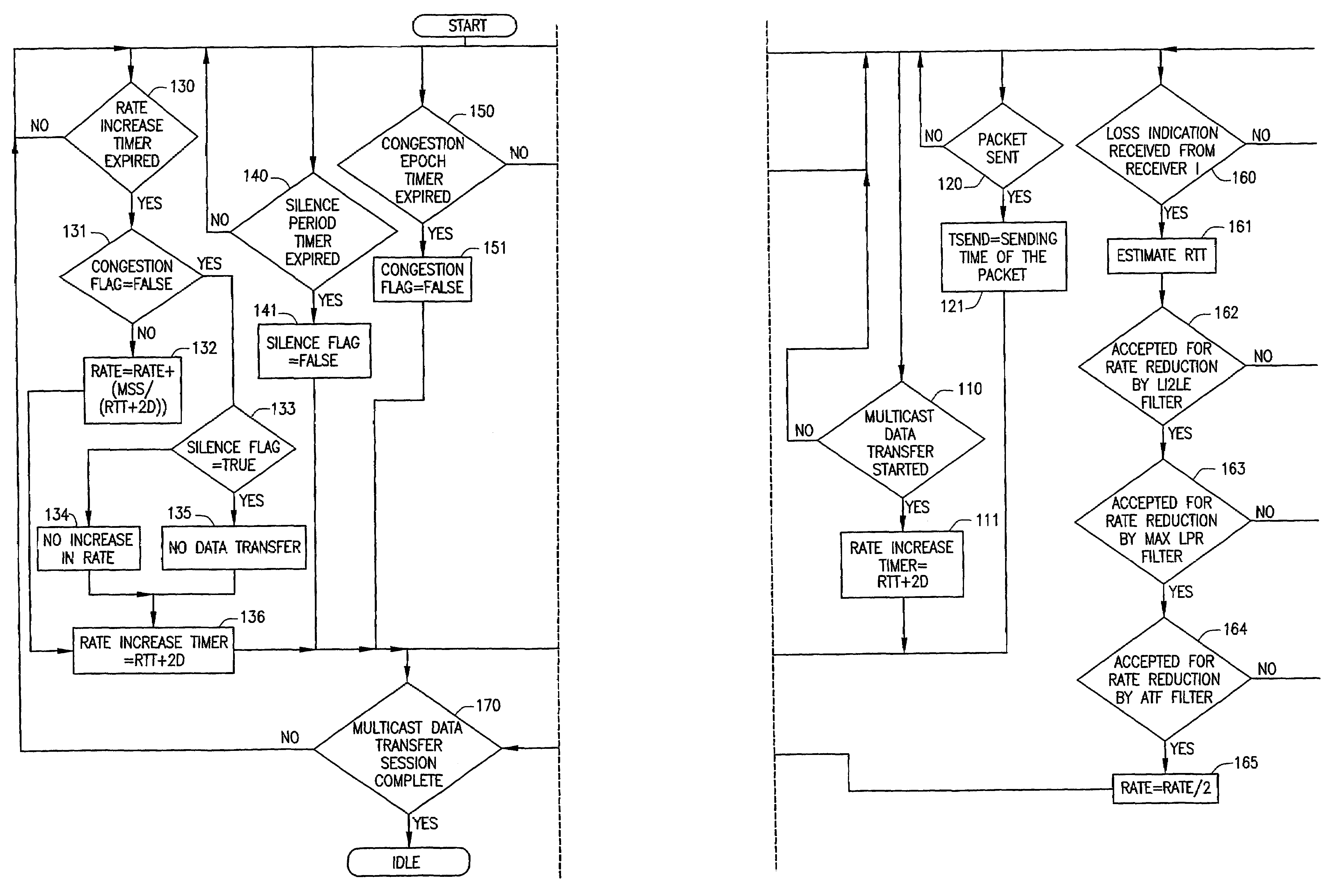
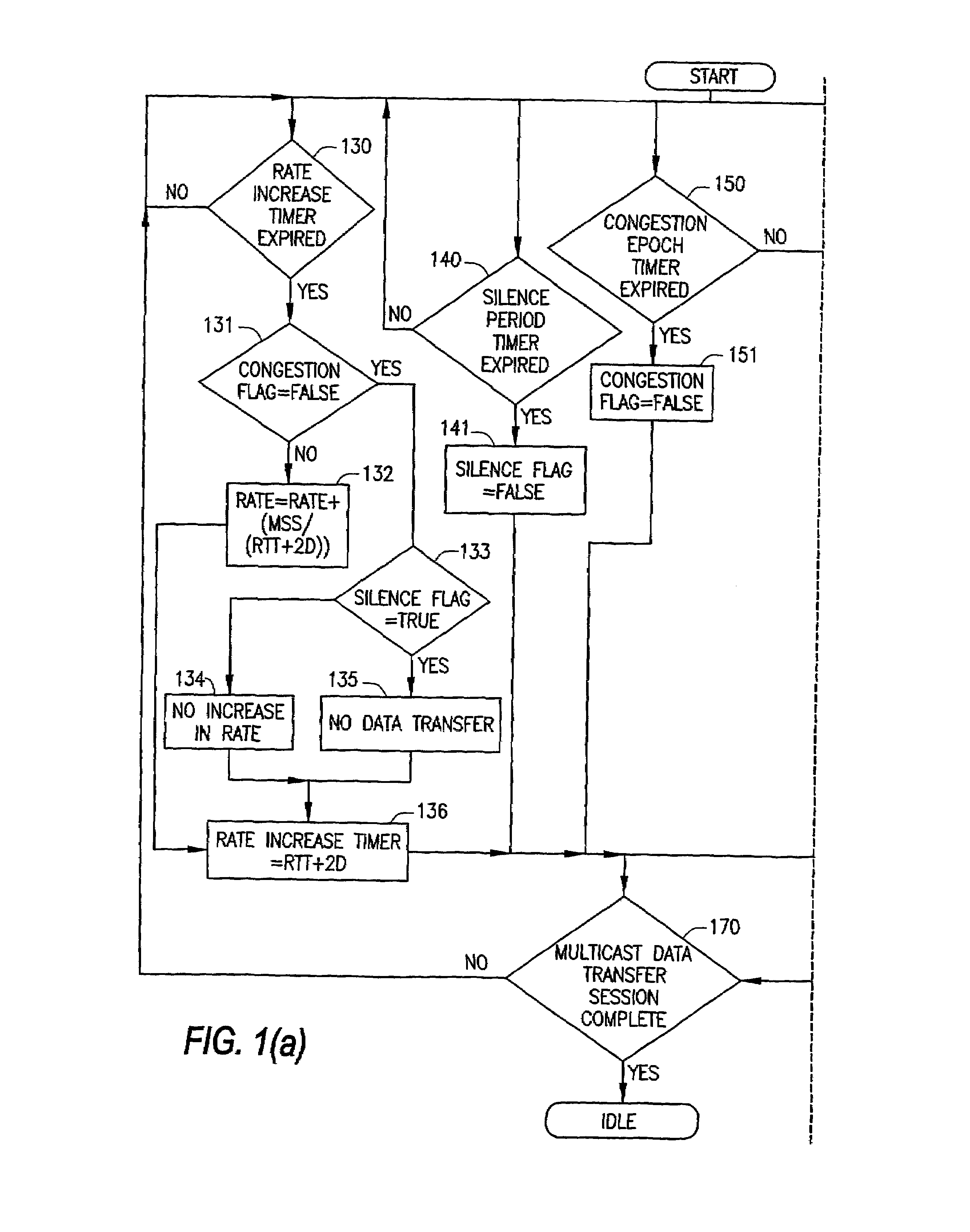
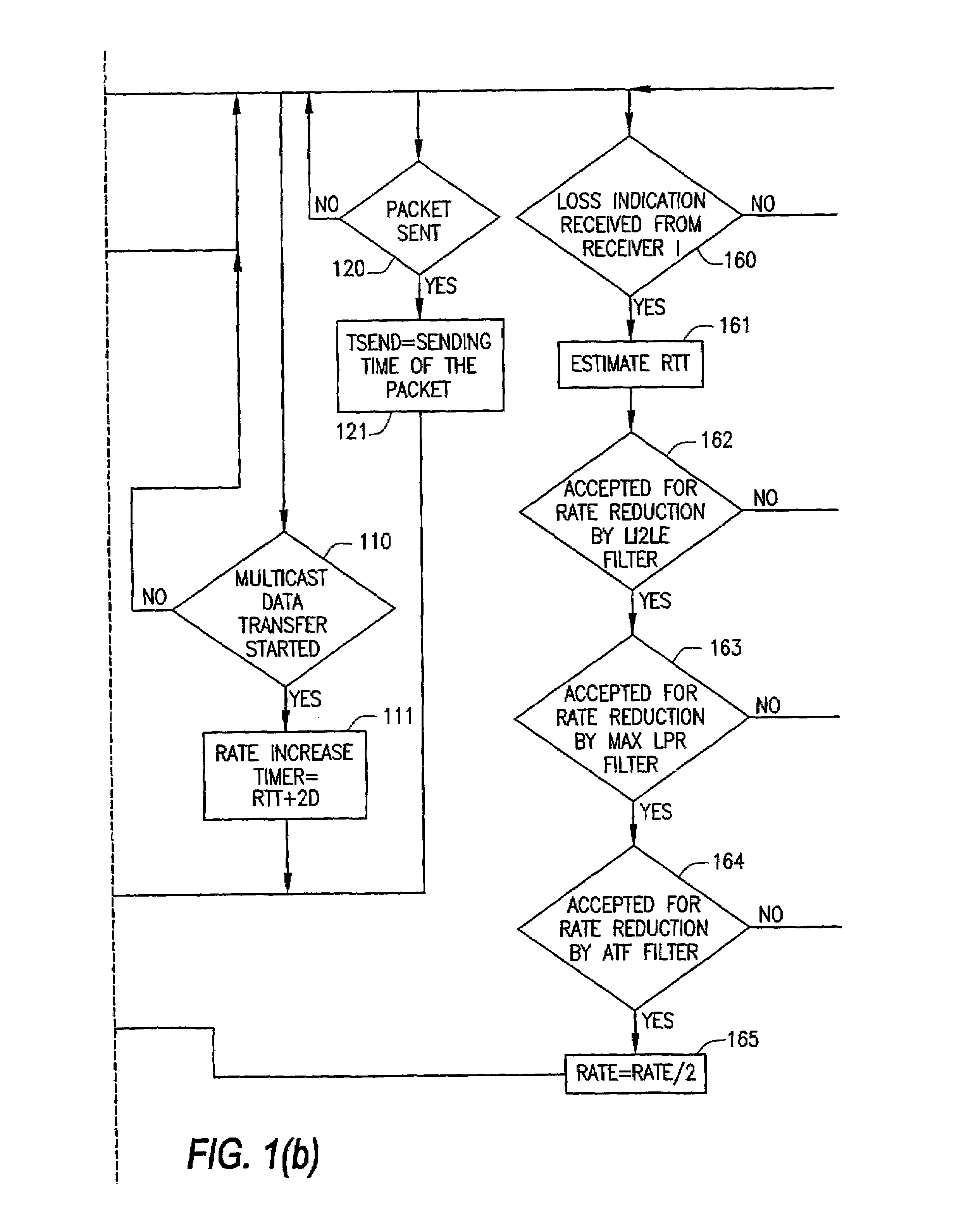
[0035]FIG. 1 illustrates the functional and logical topology of the preferred embodiment of the present invention. It is understood that those skilled in the art will know that components illustrated in FIG. 1 can be realized as hardware or software functional components.

[0036]In a preferred embodiment of the pres...


PUM


Abstract

The present invention provides for a method of congestion control for multicast transmission that is entirely managed at the source of the transmission. The various types of filters as well as round trip time estimators (130) that are used in the invention to determine when the rate of the multicast transmission should be reduced to alleviate congestion. The source of the transmission adjusts the rate of transmission based on loss indications that the receivers would otherwise transmit.

Description

CROSS-REFERENCE TO RELATED APPLICATIONS[0001]This application is a 371 of PCT / US01 / 11119 filed Apr. 6, 2001 which claims benefit of U.S. Provisional Patent Application Ser. No. 60 / 195,553 filed on Apr. 6, 2000 which claims benefit of U.S. Provisional Patent Application 60 / 247,027 filed Nov. 9, 2000.FIELD OF THE INVENTION[0002]The present invention involves a system and method of source-based multicast congestion control.BACKGROUND OF THE INVENTION[0003]As a greater number of people begin to access the Internet through high speed connections, the content offered is expanding. Video and audio broadcasting over the internet is extremely appealing because the potential audience is extremely large and the cost of broadcasting is far less than traditional broadcasting methods. One method of broadcasting video and audio streams over the Internet is Multicasting.[0004]Multicasting is one of the types of packets that the Internet Protocol Version 6 (“IPv6”) supports. It is communication betw...

Claims


Application Information

Patent Timeline
Patent Type & Authority Patents(United States)
IPC IPC(8): G06F15/16H04L12/18H04L12/56
CPCH04L12/18H04L12/1886H04L47/15H04L47/263H04L47/283H04L47/10H04L12/1868Y02B60/31Y02D30/50
Inventor KALYANARAMAN, SHIVKUMARNATU, NEELKANTHRAJAGOPAL, PRIYATHAPLIYAL, PUNEETSIDHARTHA, FNULI, JIANG
Owner RENESSELAER POLYTECHNIC INST
Why Eureka
Try Eureka