Straight knife with liner lock

Inactive Publication Date: 2006-04-04
ROBERSON ROBBIE E
View PDF13 Cites 30 Cited by
  • Summary
  • Abstract
  • Description
  • Claims
  • Application Information

AI Technical Summary

Benefits of technology

[0013]A straight knife is disclosed including a pivotable blade with opposed ends each forming a selected tool that can be single-handedly manipulated by a user to expose either end. The knife includes a handle having a blade channel defined along its longitudinal axis and having a pivot end and a base end. A pivotable blade having opposed end sections integrally formed with a body section is pivotably connected within the blade channel. The blade is secured from freely pivoting relative to the handle during use by engagement of at least one lock opening disposed on the blade body section with an engagement end of a locking member positioned in the blade channel. The e

Problems solved by technology

Folding knives generally offer a variety of cutting or other tool ends each designed for a special purpose; however, folding knives offer this variety at the expense of the strength offered by a full tang knife.
However, a major drawback of straight knives is the limitation of having only one singular-purpose blade.
Further, carrying multiple knives adds unnecessary weight to the hunter's load and increases the chance of losing valu

Method used


Image

  • Straight knife with liner lock
  • Straight knife with liner lock
  • Straight knife with liner lock

Examples


Embodiment Construction

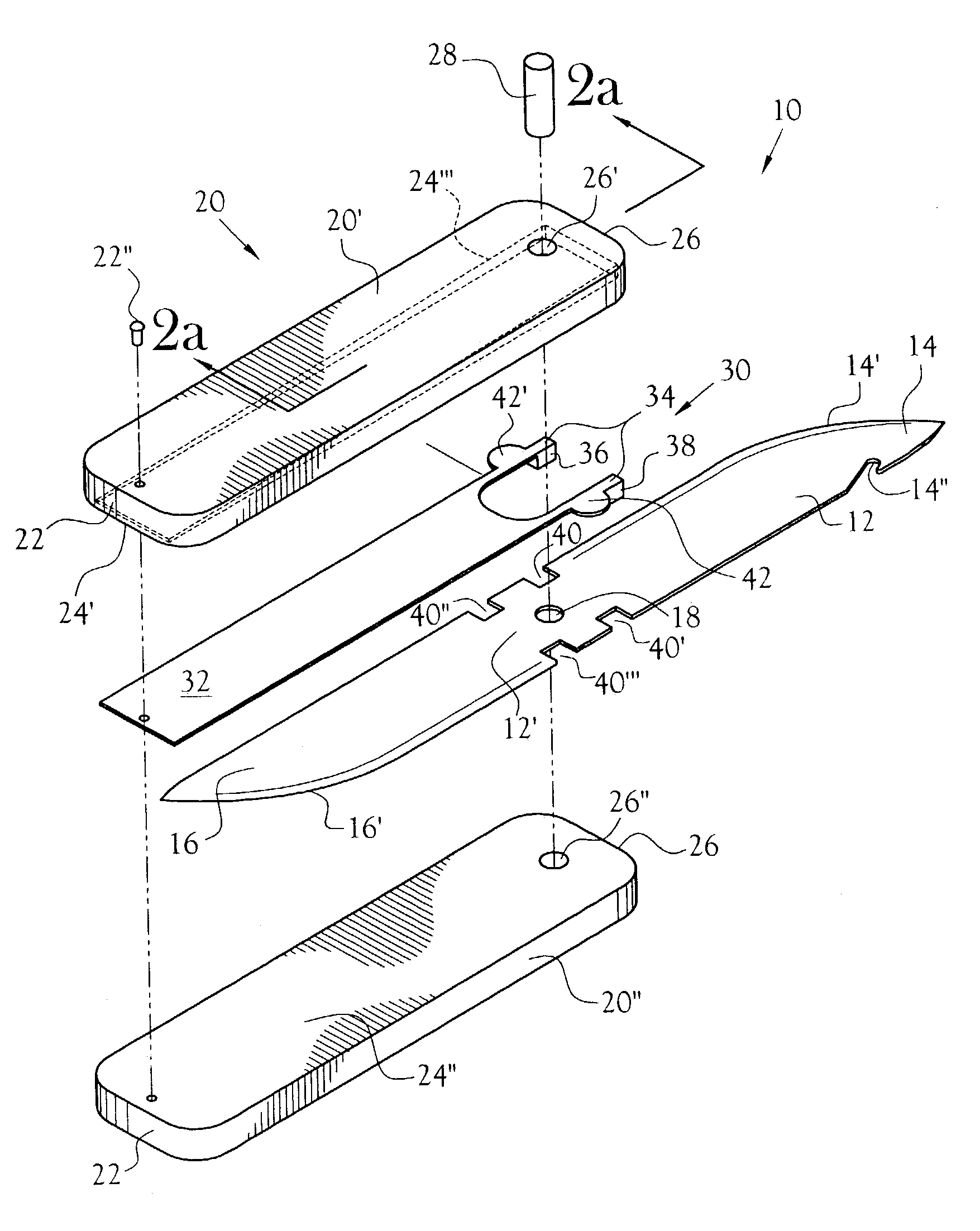
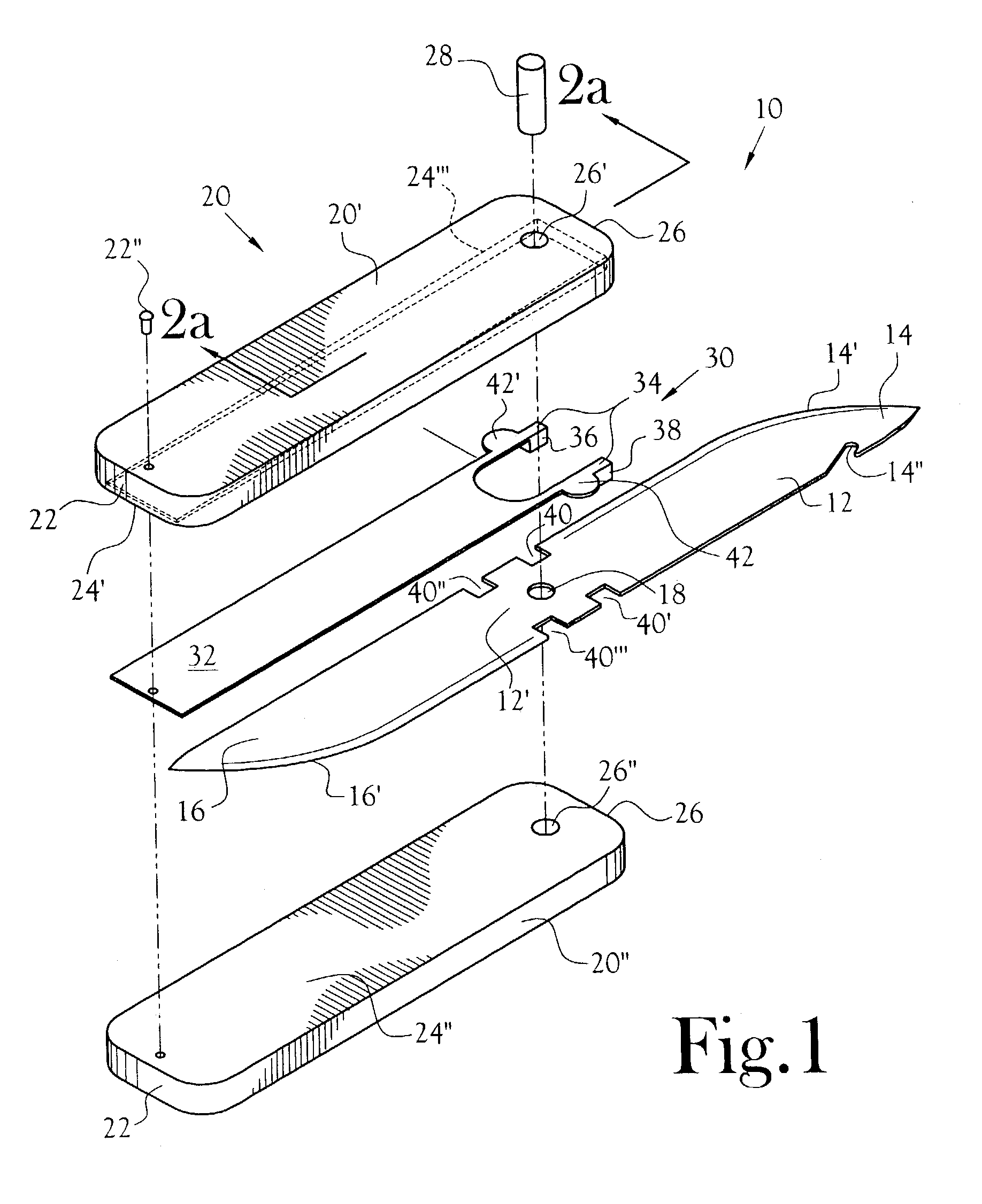
[0029]A straight knife 10 is disclosed including a pivotable double-ended blade 12 that can be single-handledly manipulated by a user to expose either one of the blade end sections 14, 16 from an end of an enclosing handle 20. The straight knife is illustrated in an exploded view at 10 in FIG. 1. The blade 12 includes opposed end sections 14, 16 that may include any of a variety of tool elements including opposed blade cutting edges 14′, 16′, a gutting hook 14″, or other tool surfaces known to be utilized by hunters and emergency personnel. The opposed end sections 14, 16 are integrally formed with a body section 12′ to provide a rigid, full-length blade member that is pivotably connected within the handle 20 by a pivot member 28 inserted through a blade pivot opening 18. A preferred position for the pivot opening 18 is a central position on the body section 12′ that is aligned along the longitudinal axis of the blade 12. The pivot opening 18 can be positioned off-center from the ce...


PUM


Abstract

A straight knife is disclosed including an interchangeable, pivoting double-ended blade and having a locking member within a handle. A pivot member is inserted through a blade body section to allow pivoting of either blade end to an operative position extended from a blade channel defined by the handle. The locking member is positioned adjacent the blade body section within the blade channel and is composed of a resilient spring material. Upon single-handed manipulation by the user, the locking member is moved from an engaged and locked position to a disengaged position apart from the blade for pivoting of the blade to expose either blade end to an operative position. The blade is removable from the handle upon removal of the pivot member and manipulation of the locking member for inserting another like-configured pivotable blade in the blade channel for single-handedly pivoting the blade to exposed a selected blade end.

Description

CROSS REFERENCE TO RELATED APPLICATIONS[0001]Not ApplicableSTATEMENT REGARDING FEDERALLY SPONSORED RESEARCH OR DEVELOPMENT[0002]Not ApplicableBACKGROUND OF THE INVENTION[0003]1. Field of Invention[0004]This invention relates to knives having folding blades. More specifically, the present invention relates to a straight knife having a pivotable double-ended blade that is single-handedly pivoted and locked by a user for selecting either one of opposed blade ends for accomplishing a multitude of tasks.[0005]2. Description of the Related Art[0006]Folding knives generally offer a variety of cutting or other tool ends each designed for a special purpose; however, folding knives offer this variety at the expense of the strength offered by a full tang knife. Conversely, straight knives are designed for strength and size. They are generally larger than folding knives and have a fixed blade with a full length which provides excellent strength for rugged activities, such as for hunting. Howeve...

Claims


Application Information

Patent Timeline
IPC IPC(8): B26B3/06B26B1/04B26B5/00
CPCB26B5/00B26B1/044
Inventor ROBERSON, ROBBIE E.
Owner ROBERSON ROBBIE E
Why Eureka
Try Eureka