Demountable building

a technology of building and movable structure, which is applied in the direction of building components, superstructure subunits, monocoque constructions, etc., can solve the problems of difficult construction of actual facilities and impracticality of approaches, and achieve the effect of facilitating both installation and removal, facilitating maintenance of the building, and transportability of the building

Inactive Publication Date: 2006-04-04
AARON SMITH PTY LTD
View PDF23 Cites 33 Cited by
  • Summary
  • Abstract
  • Description
  • Claims
  • Application Information

AI Technical Summary

Benefits of technology

[0020]In a preferred embodiment, the demountable building is transportable. The building may be transported by any means either as a complete structure and / or in a disassembled state where the units are transported separately. The transportability of the building and the units facilitates both its installation and removal. It also assists maintenance of the building by allowing individual units to be easily removed and replaced. Examples of suitable transport means include truck, train, boatship or plane, or combinations thereof.
[0021]Preferably, the base member may include a sliding means that allows the structure to be slid and / or lifted onto a transport means. Ideally the sliding means is a heavy-duty sled or skids incorporating tow lugs. This facilitates the sliding or lifting of the demountable building onto an appropriate transport means such as an industrial tilt tray truck. Alternatively, the base member may be equipped with wheels to allow towing or lifting onto a transport means. As a further alternative, the demountable building may be towable itself. A levelling arrangement may be applied to level the building on uneven or sloping ground.

Problems solved by technology

This approach has proven impractical in many cases particularly where the locations are remote and / or there is no readily available water or power supply in these regions.
This has not only created problems in providing living and working conditions in these regions, but also makes construction of the actual facilities problematic.

Method used


Image

  • Demountable building
  • Demountable building
  • Demountable building

Examples


Embodiment Construction

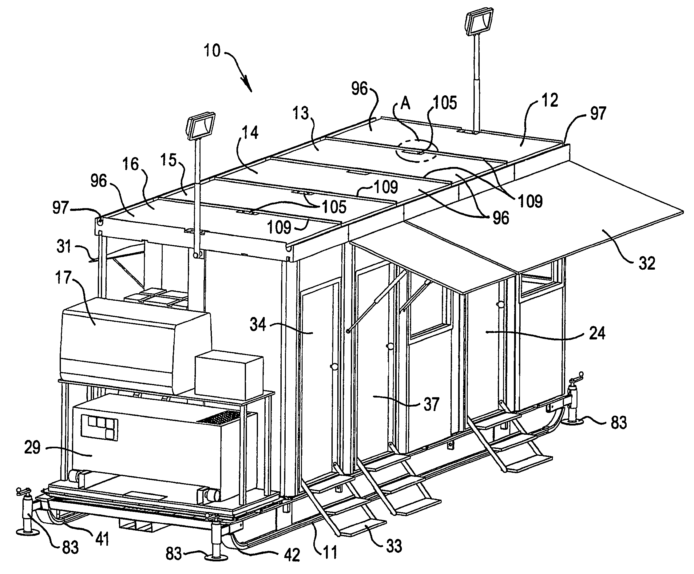
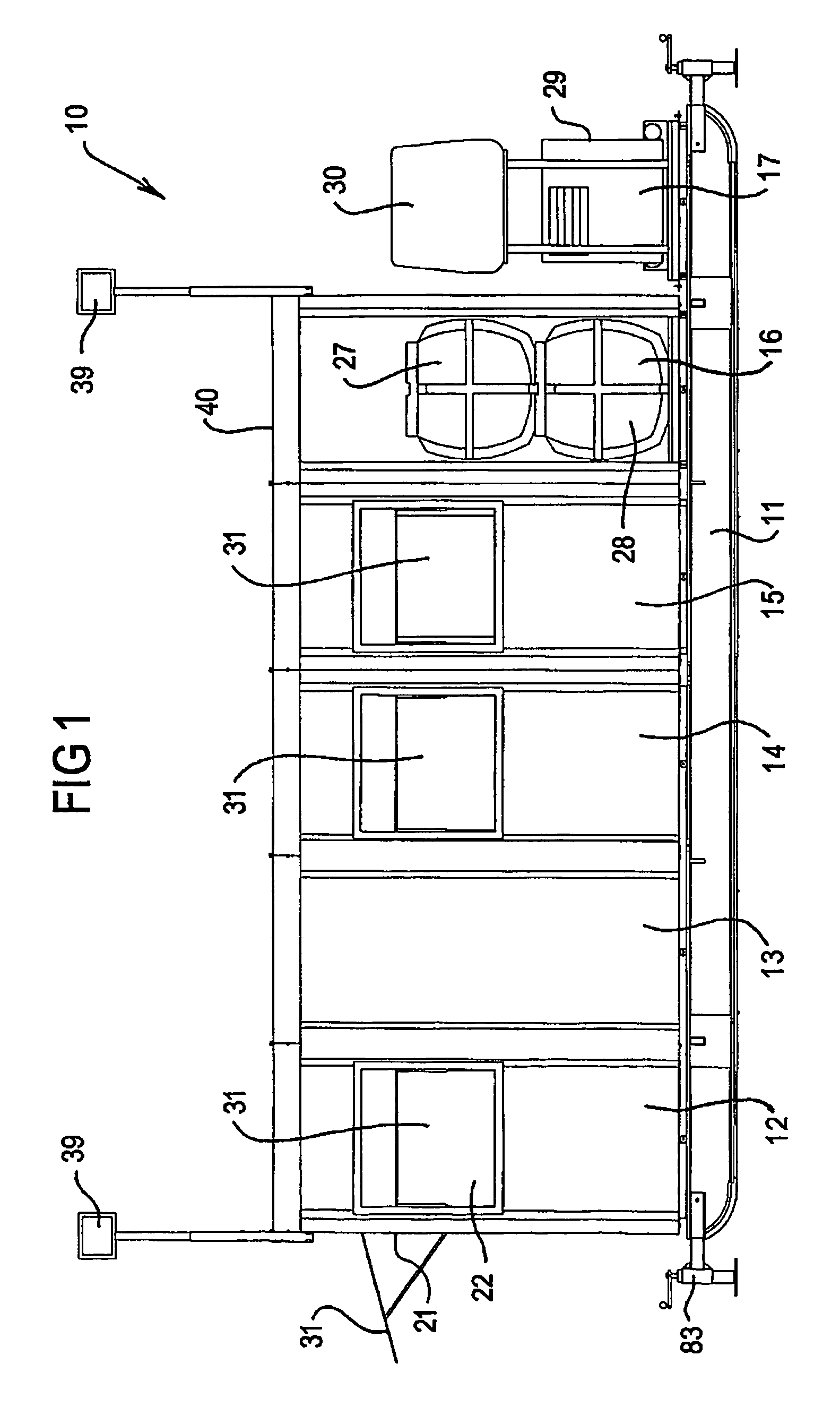
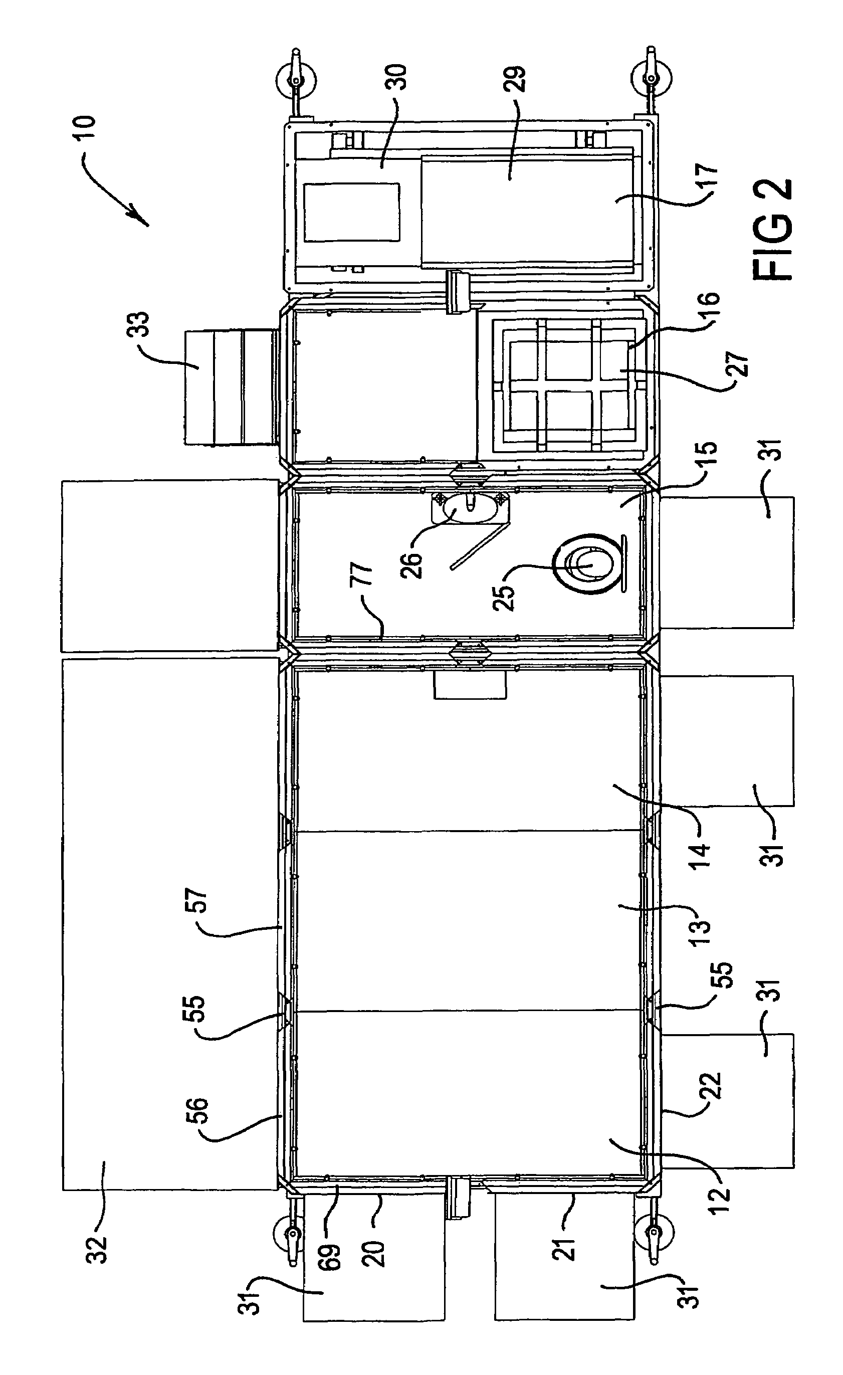
[0048]Referring initially to FIGS. 1 to 5, there is shown a demountable building 10 which has a base 11 and a series of modular compartments 12 to 16 and a modular unit 17, each of which is releasably mounted to the base 11. The modular components include three compartments 12 to 14 which may for example comprise two compartments combined to form one large compartment for work personnel to work or relax, and a third compartment which could be a utilities compartment. The compartment 15 as shown is a toiletry compartment, while the compartment 16 includes water / waste storage tanks and a resources storage unit and the unit 17 includes a diesel generator and a compressor.

[0049]The compartments 12 to 14 can be divided by partitions to create three separate modules or the partitions can be omitted to create one large module as shown, so that a room is created having a floor area equal to the combined floor area of the three compartments 12 to 14.

[0050]Each compartment / unit (hereinafter “...


PUM


Abstract

A structure such as a demountable building (10) including a base (11), a plurality of modular units (12–17) which are arranged for connection to the base (11). Each unit is fitted out with functional elements to enable that unit to perform a predetermined function in the operation of the building (10). Each unit (12–17) and its associated functional elements being operative to be connected to, or removed from, the base (11) as a single unit.

Description

[0001]The present invention relates generally to modular buildings and in particular to demountable buildings and has been designed especially, but not exclusively, for use as buildings in remote locations.BACKGROUND[0002]Demountable buildings are typically permanent or semi-permanent structures which are used in activities requiring on site equipment and / or personnel for extended periods of time. These types of facilities are required in activities such as mining, construction, exploration, research, emergency services, aid organisations and armed services operations.[0003]Permanent or semi-permanent structures of the prior art are erected at the site, and the various utilities such as power and water supply are shipped in separately. This approach has proven impractical in many cases particularly where the locations are remote and / or there is no readily available water or power supply in these regions. This has not only created problems in providing living and working conditions i...

Claims


Application Information

Patent Timeline
Patent Type & Authority Patents(United States)
IPC IPC(8): E04B1/343B62D24/04E04B1/14E04H1/12E04H5/02
CPCE04B1/14E04B1/34331E04H1/1216E04H5/02E04H1/1205E04H2001/1283
Inventor SMITH, AARON MICHAELSMITH, MICHAEL RADFORDSHIPWAY, ADAM
Owner AARON SMITH PTY LTD
Why Eureka
Try Eureka