Fin-and-tube type heat exchanger

a heat exchanger and fin-and-tube technology, which is applied in the field of fin-and-tube heat exchangers, can solve the problems of increasing the pressure drop across the fins as the penalty paid for the increased heat transfer, complex and expensive manufacturing of louvers, and not optimizing the heat transfer, so as to reduce the air pressure drop, increase the heat transfer, and optimize the effect of heat transfer

Active Publication Date: 2006-04-04
MAHLE INT GMBH
View PDF17 Cites 51 Cited by
  • Summary
  • Abstract
  • Description
  • Claims
  • Application Information

AI Technical Summary

Benefits of technology

[0007]A fin-and-tube type heat exchanger comprising a plurality of fins disposed adjacent to each other. Each of the fins define a plane and have an upstream portion and a downstream portion. A plurality of louvers are formed in each of the fins with each louver extending at an angle with respect to the planes of the fins. A plurality of tubes pass through the plurality of fins interconnecting the fins wherein the upstream portions of the plurality of interconnected fins define an incoming airflow side of the heat exchanger and the downstream portions of the plurality of interconnected fins define an outgoing airflow side of the heat exchanger. The plurality of louvers define a first bank of louvers formed in each of the upstream portions of the fins facing the incoming airflow side of the heat exchanger. The plurality of louvers also define a second bank of louvers formed in each of the downstream portions of the fins facing the incoming airflow side of the heat exchanger such that all of the louvers are facing the same direction toward the incoming airflow side whereby the louvers effectively redirect and mix an incoming flow of air and minimize an air pressure drop across the fins for increasing a heat transfer between the tubes, fins, and flow of air.
[0008]Accordingly, the subject invention provides a simplified louver design for optimizing the heat transfer between the surfaces of the heat exchanger and the air flow. More specifically, the subject invention increases heat transfer while actually reducing the air pressure drop.

Problems solved by technology

One issue that arises when disrupting the air flow is a pressure drop across the fins.
A significant increase in the pressure drop across the fins is the penalty paid for the increased heat transfer.
Although these designs may provide some advantages, the louver configurations are complex and expensive to manufacture and do not optimize the heat transfer between the surfaces of the heat exchanger and the air flow.

Method used


Image

  • Fin-and-tube type heat exchanger
  • Fin-and-tube type heat exchanger
  • Fin-and-tube type heat exchanger

Examples


Embodiment Construction

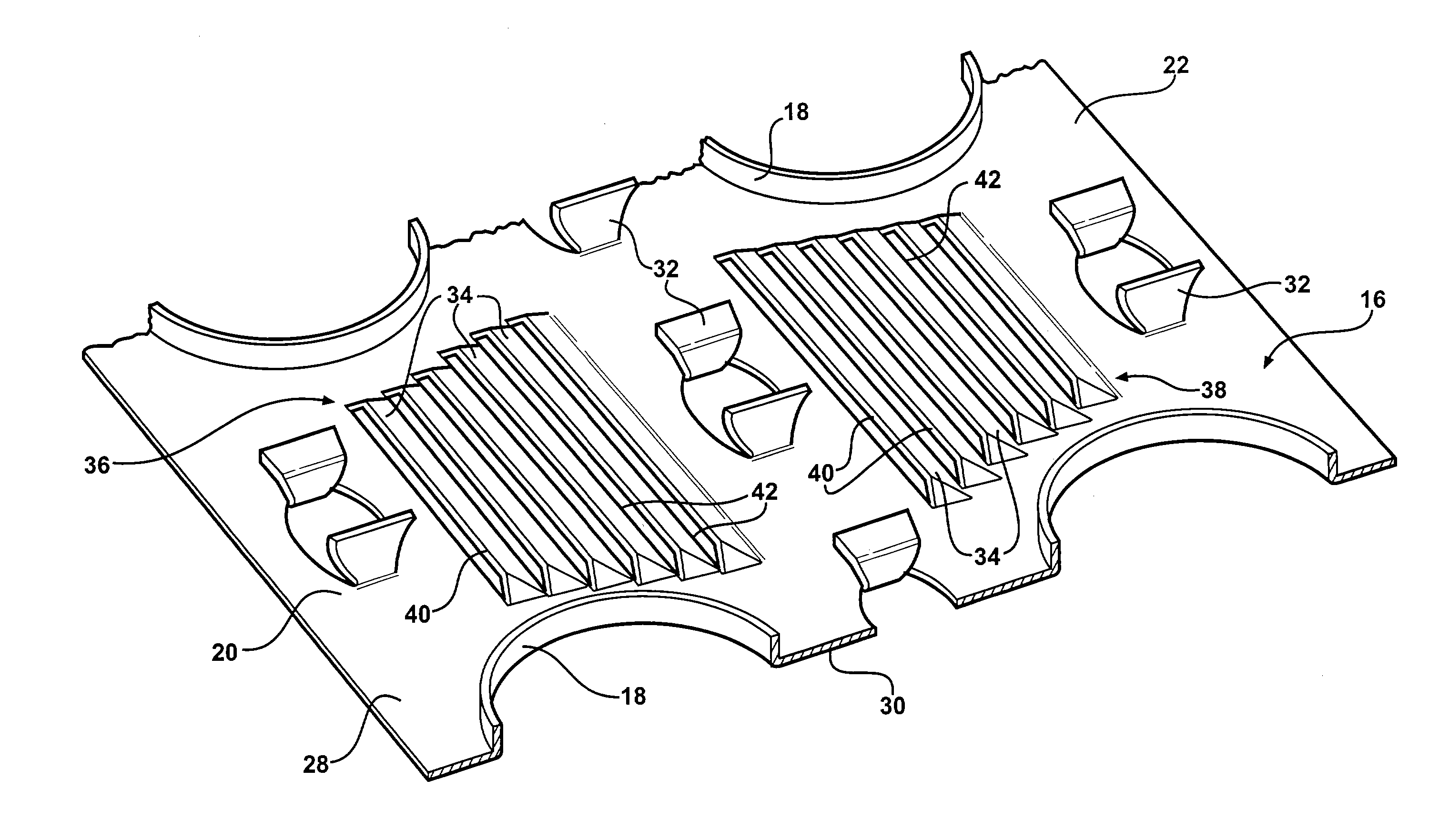
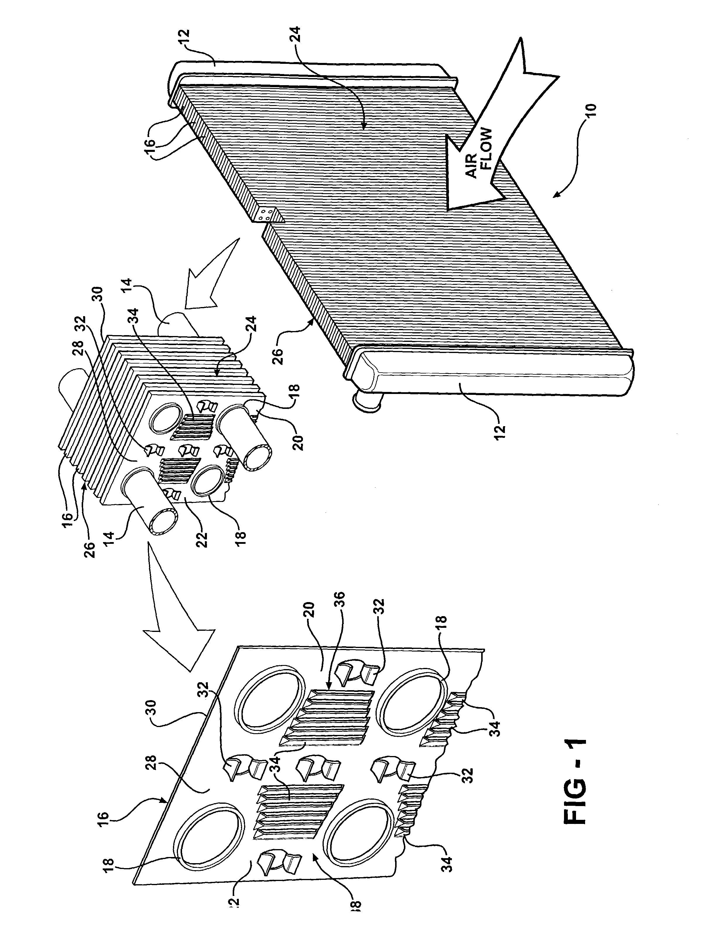
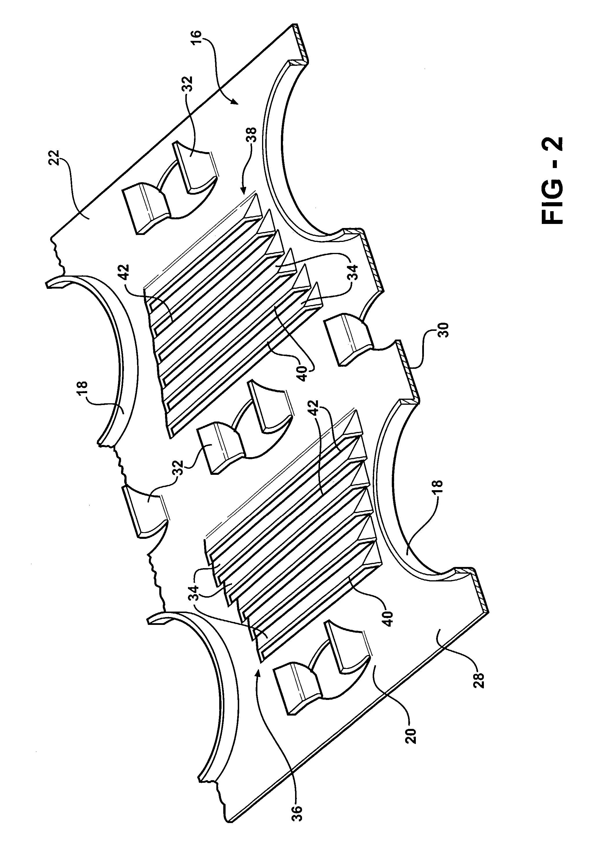
[0014]Referring to the Figures, wherein like numerals indicate like or corresponding parts throughout the several views, a heat exchanger is generally shown at 10 in FIG. 1. The heat exchanger 10 includes a pair of manifolds 12 and a plurality of tubes 14. The tubes 14 are interconnected at opposite ends to the manifolds 12 to pass coolant between the manifolds 12. The heat exchanger 10 also includes a plurality of fins 16 disposed adjacent to each other. The plurality of tubes 14 pass through the plurality of fins 16 for interconnecting the fins 16 together and mounting the fins 16 to the heat exchanger 10. In particular, the fins 16 define collars 18 with the tubes 14 being received within and fixedly secured to the collars 18. This general configuration of a heat exchanger defines what is known in the art as a fin-and-tube type heat exchanger. It should be appreciated that the exact configuration of the manifolds 12, tubes 14, and fins 16, could be of any suitable design without ...


PUM


Abstract

A heat exchanger having fins disposed adjacent to each other with tubes passing through the fins to interconnect the fins. Louvers are formed in each of the fins with each louver extending at an angle with respect to the fins. An upstream portion of the interconnected fins define an incoming airflow side of the heat exchanger and a downstream portion of the interconnected fins define an outgoing airflow side of the heat exchanger. The louvers define a first bank of louvers formed in each of the upstream portions of the fins facing the incoming airflow side of the heat exchanger. The louvers also define a second bank of louvers formed in each of the downstream portions of the fins facing the incoming airflow side of the heat exchanger. Hence, all of the louvers on the fins are facing the same direction for minimizing the air pressure drop, while increasing a heat transfer between the fins, tubes, and the air flow.

Description

BACKGROUND OF THE INVENTION[0001]1. Field of the Invention[0002]The subject invention relates to heat exchangers of the fin-and-tube type with an improved louver configuration.[0003]2. Description of Related Art[0004]Fin-and-tube type heat exchangers are well known in the art. These heat exchangers having a number of fins with heat transfer tubes passing therethrough. The fins typically incorporate a number of louvers to redirect and mix the air flow across the fins to increase the heat transfer between the surfaces of the heat exchanger, which include the surfaces of the fins and the outside surfaces of the tubes, and the air flow. One issue that arises when disrupting the air flow is a pressure drop across the fins. A significant increase in the pressure drop across the fins is the penalty paid for the increased heat transfer.[0005]Accordingly, there has been much development in louver designs to balance the heat transfer and air pressure drops in an attempt to obtain the optimum ...

Claims


Application Information

Patent Timeline
Patent Type & Authority Patents(United States)
IPC IPC(8): F28D1/04F28F1/32
CPCF28F1/325
Inventor PAPAPANU, STEVEN JAMESLI, LONGHU
Owner MAHLE INT GMBH
Why Eureka
Try Eureka