

Conveyor with gear mechanism gripper and related conveyor link
a conveyor and gear mechanism technology, applied in mechanical conveyors, conveyors, furnaces, etc., can solve problems such as side effects, inability to achieve, and disfavored frictional or high frictional surfaces, and achieve the effect of convenient and reliable manufacturing
- Summary
- Abstract
- Description
- Claims
- Application Information
AI Technical Summary
Benefits of technology
Problems solved by technology
Method used
Image

Examples
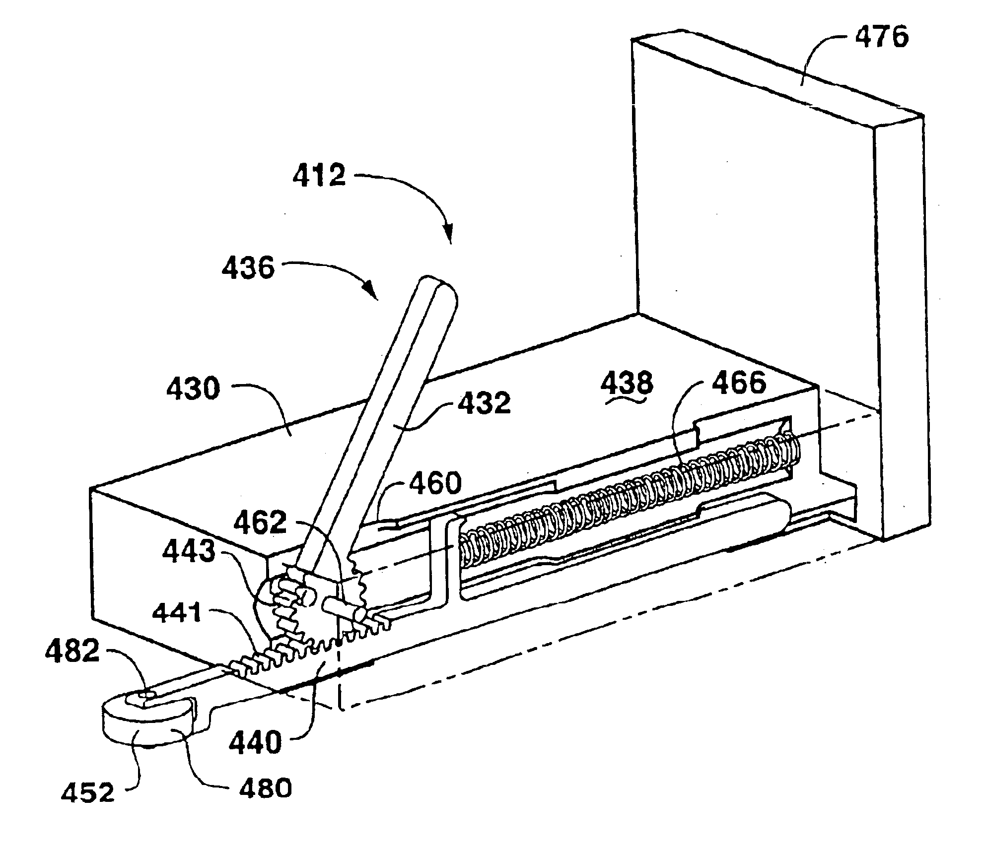
third embodiment
[0057]Reference will now be made in detail to embodiments of the invention, one or more examples of which are illustrated in the drawings. Each example is provided by way of explanation of the invention, and not meant as a limitation of the invention. For example, features illustrated or described as part of one embodiment can be used with another embodiment to yield still a third embodiment It is intended that the present invention include these and other modifications and variations. In discussing various embodiments, like or similar reference numerals are used below with like or similar parts of various embodiments.
[0058]As shown in the various figures, numerous embodiments of a gripper conveyor and conveyor link with a gripping member are disclosed. It should be understood that the present invention encompasses both a gripper conveyor chain-type structure, and individual links for such a chain. It should also be understood that various different methods of attaching such links t...
first embodiment
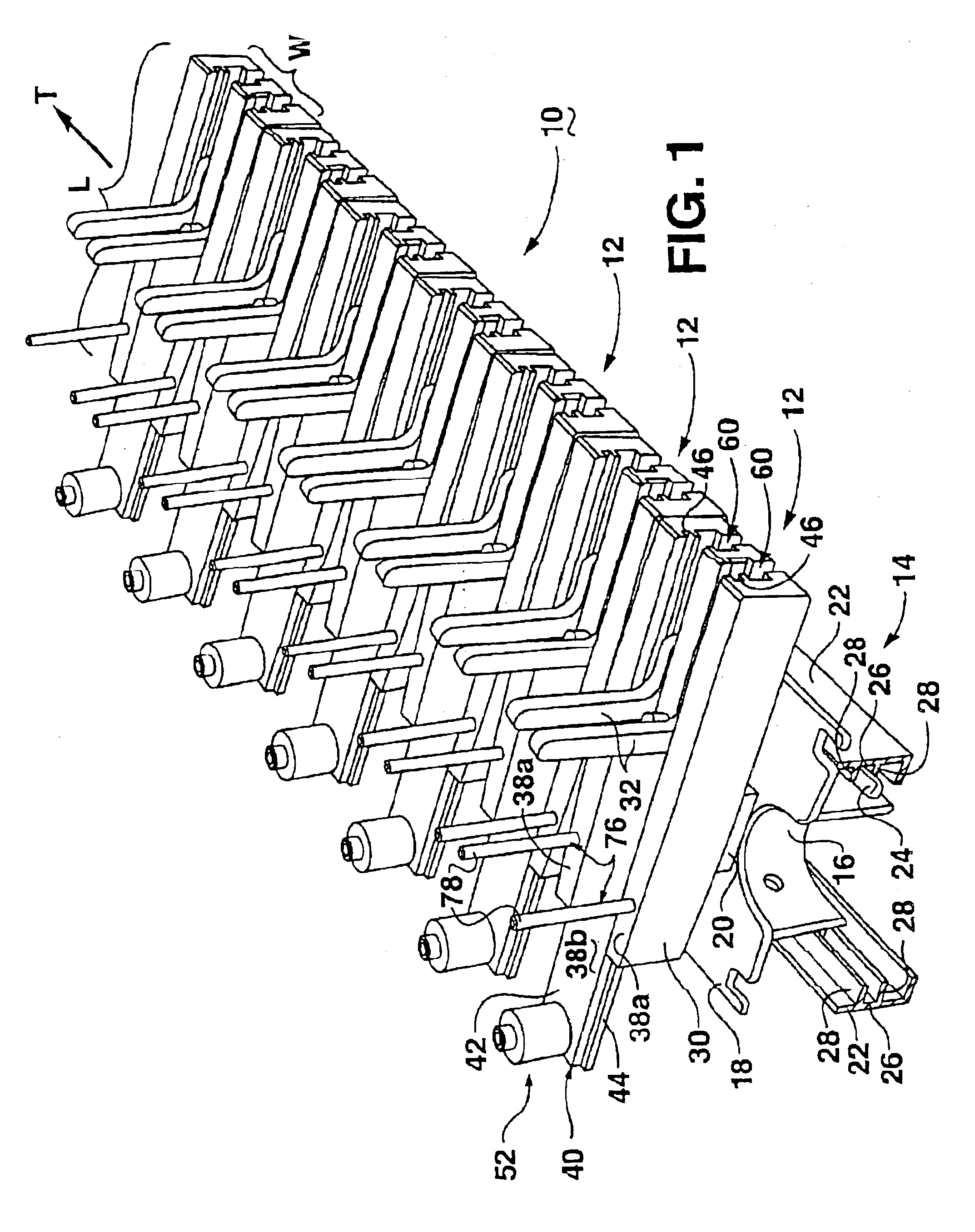
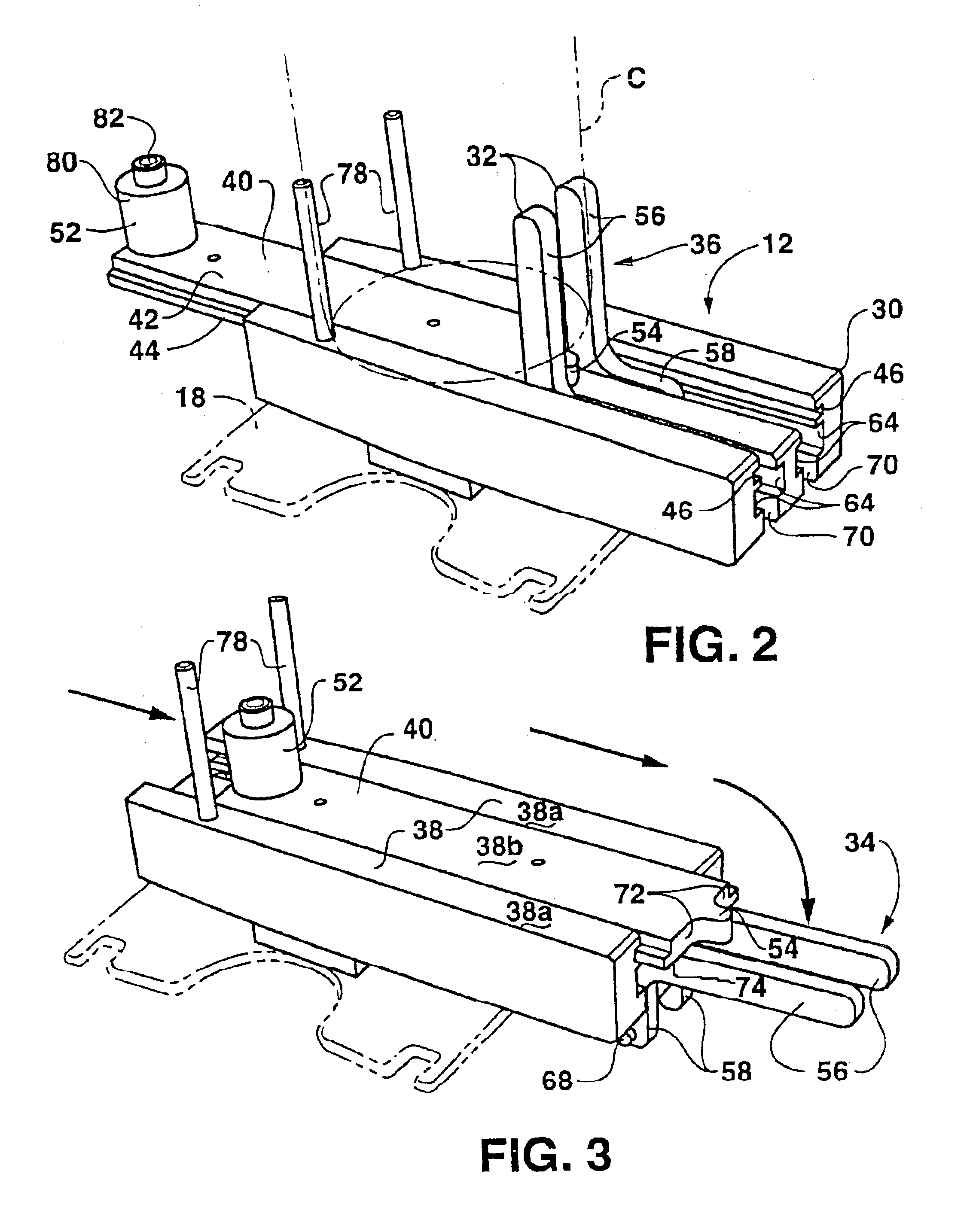
[0059]With particular reference to FIGS. 1-8, a gripper conveyor and conveyor link are shown. According to this embodiment of the invention, a conveyor 10 includes a plurality of links 12 and a drive mechanism 14. As illustrated in FIG. 1, drive mechanism 14 includes a knuckle conveyor 16 attached to a platform member 18, which may be constructed as set forth in U.S. Pat. No. 6,601,697 or in various other ways. It should be understood that drive mechanism 14 can have many shapes and forms according to the present invention. For example, instead of knuckle conveyor 16, other types of conveyors, belts, or chains such as roller chains, or roller chains with attachments, could be used for drive mechanism 14.
[0060]In the example shown, knuckle conveyor 16 is driven within rails 22, and is guided by flanges 24 extending from knuckle conveyor 16 into channels 26 defined by walls 28 of rails 22. As is known in the art, the drive mechanism may traverse a straight or curved line from one end ...
PUM
 Abstract
Description
Claims
Application Information