Printer jet detection method and apparatus

a detection method and printer technology, applied in printing, electrical equipment, power drive mechanisms, etc., to achieve the effect of reducing the amount of x-axis scanning displacement, improving printing speed, and reducing the cost of print head hardwar

Active Publication Date: 2006-04-04
XEROX CORP
View PDF6 Cites 36 Cited by
  • Summary
  • Abstract
  • Description
  • Claims
  • Application Information

AI Technical Summary

Benefits of technology

[0008]Similar to single pass printers, multi-pass printers may employ multiple staggered print heads to further improve the printing speed. Staggered print heads may effectively extend over large portions of the X-axis dimension to reduce the amount of X-axis scanning displacement while employing smaller and less expensive print head hardware.

Problems solved by technology

However, a multipass printer having twenty-four passes using some degree of X-axis displacement would only require 300 ink jets per ink color to achieve the same resolution image.

Method used


Image

  • Printer jet detection method and apparatus
  • Printer jet detection method and apparatus
  • Printer jet detection method and apparatus

Examples


Embodiment Construction

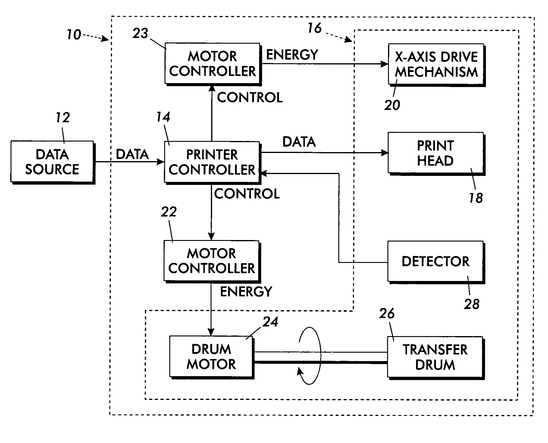
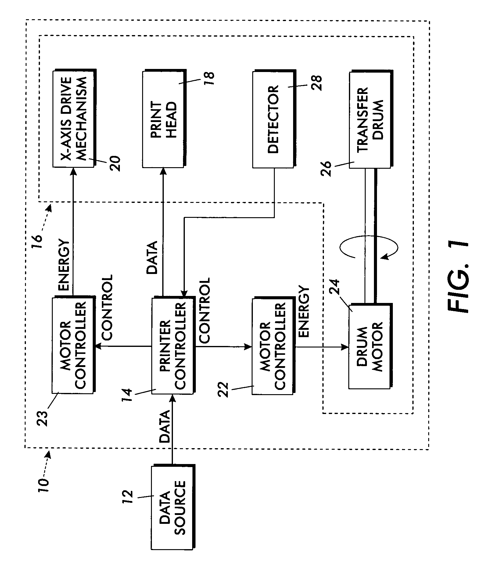
[0025]FIG. 1 shows a schematic block diagram of an exemplary offset printing apparatus 10. In particular, the offset printing apparatus includes a detector 28 and a processing circuit in the form of a printer controller 14 that are configured to, among other things, measure alignment and / or registration between various jets of the printing apparatus. An example of various details of an offset printer which may be employed in the diagram of FIG. 1 are provided in U.S. Pat. No. 5,389,958 entitled IMAGING PROCESS, which is assigned to the assignee of the present invention. FIGS. 3 and 4 illustrate in further detail a nonlimiting example of the mechanical configuration of a print engine 16 that may be used in the printing apparatus 10. However, it will be appreciated that one or more of the inventive features described herein may be incorporated on any printing apparatus in which alignment and / or registration between jets of one or more print heads may be tested.

[0026]In addition to the...


PUM


Abstract

A method includes ejecting ink from a first set of one or more nozzles to form a first image pattern at least partially within an image field. The method likewise includes ejecting ink from a second set of one or more nozzles to form a second image pattern at least partially within the image field. The first image pattern and second image pattern form a composite pattern within the image field. Then, an optical detector obtains a measurement of an optical characteristic of the image field. The measurement may be compared with a reference optical characteristic for the composite pattern within the image field.

Description

BACKGROUND AND SUMMARY[0001]The present disclosure relates generally to ink jet printers, and more particularly, to detection of ink jet operation within ink jet printers.[0002]Ink-jet printing systems commonly utilize either direct printing or offset printing architectures. In a typical direct printing system, ink is ejected from jets in the print head directly onto the final receiving medium. In an offset printing system, the print head jets the ink onto an intermediate transfer surface, such as a liquid layer on a drum. The final receiving medium is then brought into contact with the intermediate transfer surface and the ink image is transferred and fused or fixed to the medium.[0003]In some direct and offset printing systems, the print head moves relative to the final receiving medium or the intermediate transfer surface in two directions as the print head jets are fired. Typically, the print head is translated at least somewhat along the X-axis, or cross-process direction, whil...

Claims


Application Information

Patent Timeline
Patent Type & Authority Patents(United States)
IPC IPC(8): B41J25/308B41J2/01B41J2/21B41J29/393H04N1/50
CPCB41J2/0057H04N1/506B41J29/393B41J2/2135
Inventor FOLKINS, JEFFREY J.
Owner XEROX CORP
Why Eureka
Try Eureka