Capsule endoscope

Active Publication Date: 2006-04-04
OLYMPUS CORP
View PDF18 Cites 54 Cited by
  • Summary
  • Abstract
  • Description
  • Claims
  • Application Information

AI Technical Summary

Benefits of technology

[0004]The present invention relates to a capsule endoscope which is to be swallowed for the purpose of obtaining images of the inside of a living body. A first object of the invention is to provide a capsule endoscope that includes a sealed space directly above the image sensor. The sealed space is for the purposes of preventing dust from clinging to the front surface of the capsule endoscope's image sensor even if a focusing adjustment is performed that tends to generate sm

Problems solved by technology

Consequently, dust or shaved particles of the lens frame that may be generated upon focusing, may cling to the front surface of the image sensor.
Therefore, there has been an instance in which this has prevented a proper image from being obtained.
Also, it is possible that such dust or shaved particles may damage the image sensor.
Furthermore, where a transparent cover for the purpose of protecting the image sensor

Method used


Image

  • Capsule endoscope
  • Capsule endoscope
  • Capsule endoscope

Examples


Example

Embodiment 1

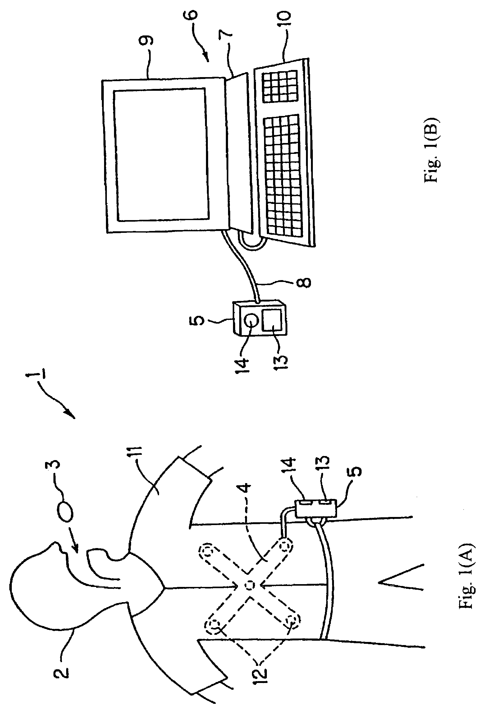
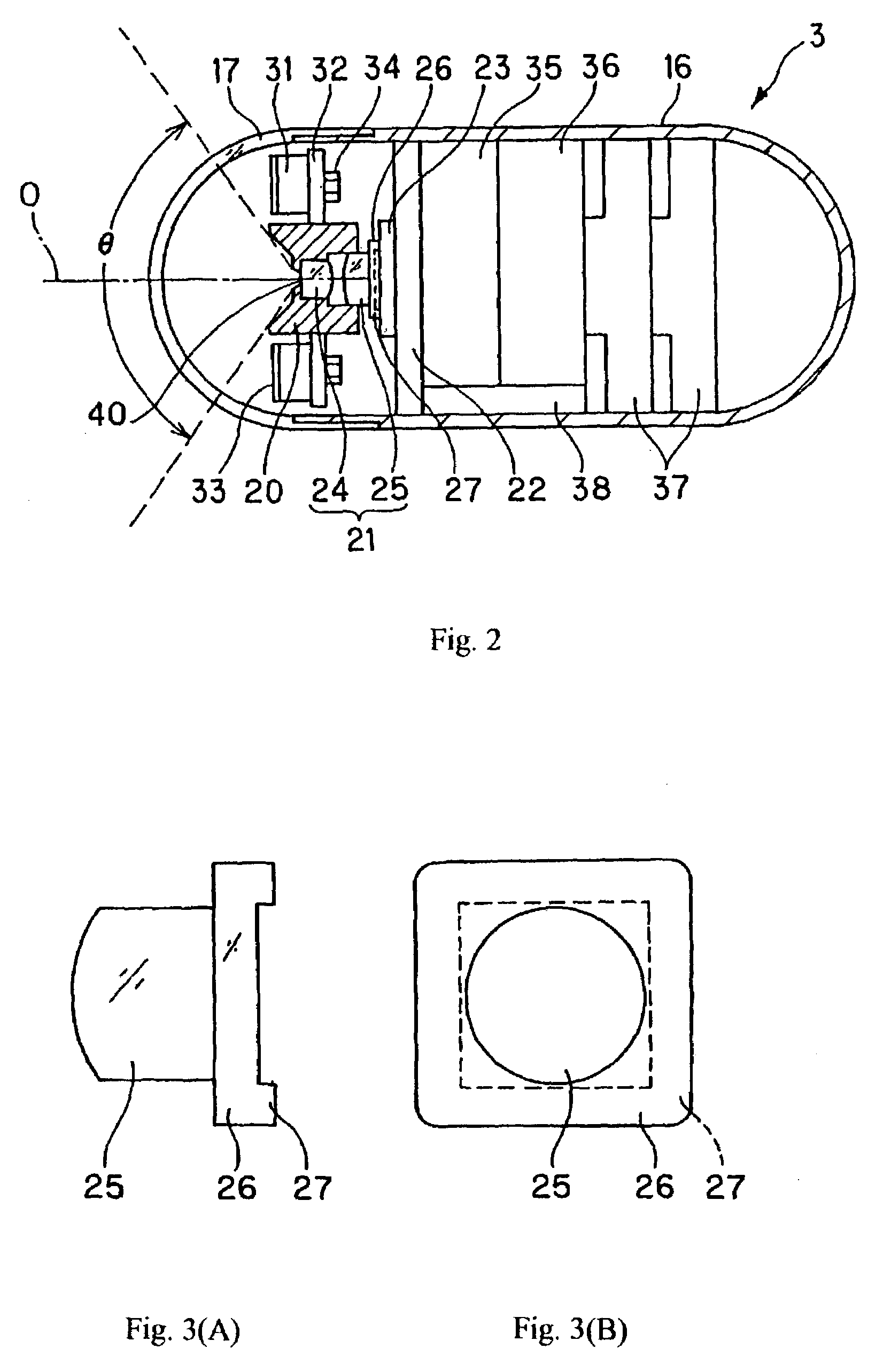
[0025]Embodiment 1 will be discussed with reference to FIGS. 1(A)–6(B). FIGS. 1(A) and 1(B) illustrate components of a capsule endoscope system for performing endoscopic examination of a living body. The capsule endoscope system 1 includes a capsule endoscope 3, which is to be swallowed and which then transmits electromagnetic waves containing image data that is taken when the capsule endoscope passes naturally through a patient's body. Image signals are transmitted by the capsule endoscope using an antenna unit 4 that is attached to a shirt 11 that is worn by a patient 2. An external unit 5, which receives signals from the antenna unit 4, is applied to the exterior of the patient 2, and functions to save images that are transmitted by the capsule endoscope 3.

[0026]As shown in FIG. 1(B), the external unit 5 is detachably connected to a personal computer (hereinafter PC), which comprises a display system 6. In the external unit 5, a hard disk of compact flash memory (R) s...

Example

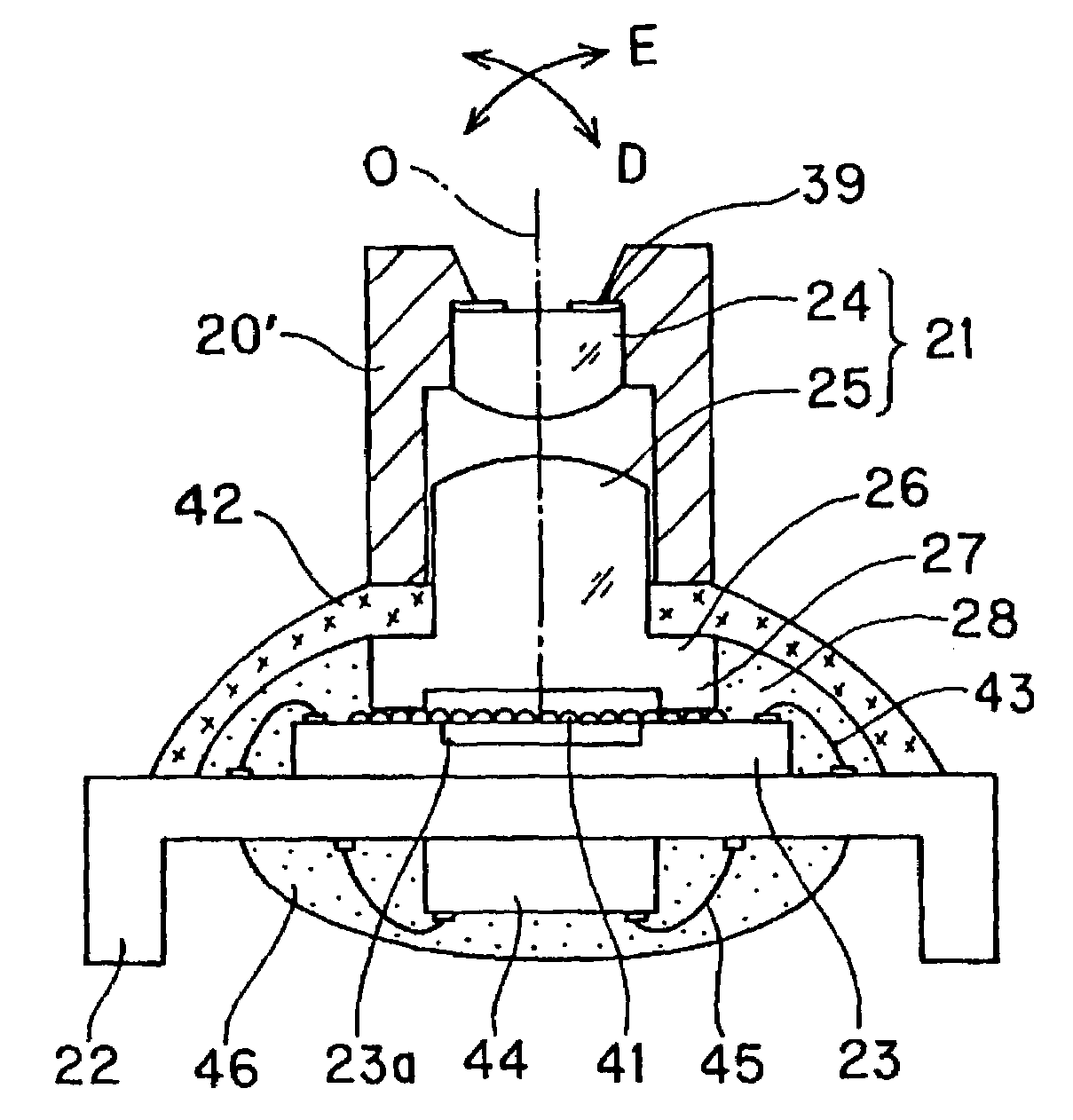
[0044]The second embodiment of the present invention will be discussed with reference to FIGS. 7 and 8(A) and 8(B). FIG. 7 is a cross-sectional view that shows the structure at the periphery of the imaging part according to Embodiment 2 of the present invention. In Embodiment 1, the cover member 26 was made to be integral with the second lens 25. However, this is not the case in the present embodiment, wherein the second lens 25 and the cover member 26 are made as separate components. Just as in Embodiment 1, the cover member 26 is installed outside of the imaging area 23a of the image sensor 23 using an adhesive 28. Then, the second lens 25 is positioned on the top surface of this cover member 26, and affixed to the cover member 26 using a transparent optical adhesive 51. Next, the lens frame 20 with the first lens 24 installed, is engaged with the second lens 25. After being moved along in the optical axis O direction so that a focusing adjusted can be performed, the lens frame 20...

Example

Embodiment 3

[0048]Embodiment 3 will be discussed with reference to FIGS. 11 and 12. FIG. 11 is a side-sectional view that shows the structure of the imaging part before the objective optical system is installed and FIG. 12 is a top plan view (i.e., looking from the top in FIG. 11) of the imaging part before the objective optical system is installed. In this embodiment, the image sensor 23 has a square, thin plate configuration; however, its imaging area 23a is formed so as to have a circular shape. The micro lens array 41, which covers the imaging area 23a, also has a circular shape. In this embodiment, multiple portions 62 that are integral to the image sensor and positioned at the four corners of the image sensor 23 at the periphery of the imaging area 23a each have a disk configuration and project upwards from the image sensor to a common height. A transparent cover member 61 having, for example, a square plate configuration, is pressed onto and adhered to the portions 62, so tha...


PUM


Abstract

A capsule endoscope includes an image sensor that is fixed to a substrate and is covered by a transparent cover member such that a sealed air space is provided between the objective optical system and the image sensor. Also, a capsule endoscope is disclosed that includes a transparent cover member, an image sensor having an imaging area that is covered by the transparent cover member; and an objective optical system which includes at least two lenses. The lens of the objective optical system that is nearest the image side is either integral with, or is adhered to, the transparent cover member. The transparent cover member seals an air space above the imaging area of the image sensor from dust which may be generated during a focusing adjustment of the two lenses. A focusing method adjusts the position of a first lens, in order from the object side, relative to that of a second lens which is nearest the image side.

Description

BACKGROUND OF THE INVENTION[0001]In recent years, endoscopes have been widely used in medical as well as industrial applications. For medical applications, a capsule endoscope has been proposed which greatly reduces the pain associated with obtaining images of internal body parts. Instead of the endoscope including an optical probe having an insertion part, the endoscope is miniaturized and contained within a capsule that is swallowed by a patient. The capsule then radio transmits images as it passes through the body to a receiver located outside the body. One example of such a capsule endoscope is Japanese Laid-Open Patent Application 2001-91860.[0002]In this conventional example, an objective lens and an illumination means formed of light emitting elements which are symmetrically located on opposite sides of the objective lens, are incorporated inside a roughly hemispherical transparent dome. An object is illuminated by the light emitting elements, and reflected light is then imag...

Claims


Application Information

Patent Timeline
IPC IPC(8): A61B1/05A61B1/00G02B23/24A61B1/04H04N5/225H04N5/335H04N7/18
CPCA61B1/04A61B1/041H04N5/2254H04N5/2253H04N2005/2255H04N23/52H04N23/555H04N23/54H04N23/55
Inventor YOKOI, TAKESHIHASEGAWA, AKIRAMATSUMOTO, SHINYASUZUKI, TAKAYUKISEGAWA, HIDETAKETAKIZAWA, HIRONOBU
Owner OLYMPUS CORP
Why Eureka
Try Eureka