Needle guide systems and methods

a technology of needle guide and guide rod, which is applied in the field of medical devices, can solve the problems of difficult to maintain the needle within the imaging beam, inaccurate tissue sample or need for reinsertion of the needle, and severe limitations in movemen

Inactive Publication Date: 2006-04-04
SONEK JIRI D
View PDF12 Cites 144 Cited by
  • Summary
  • Abstract
  • Description
  • Claims
  • Application Information

AI Technical Summary

Benefits of technology

[0007]Accordingly, it is an object of the present invention to provide improved needle guide systems

Problems solved by technology

However, it has often been difficult to maintain a needle within an imaging beam, particularly within the desired angle with respect to the imaging beam axis.
Once the needle escapes this axis, it will not be seen by the imaging device, which may result in an inaccurate tissue sample or require reinsertion of the needle.
While these devices provided some movement of the needle relative to the imaging device, suc

Method used


Image

  • Needle guide systems and methods
  • Needle guide systems and methods
  • Needle guide systems and methods

Examples


Embodiment Construction

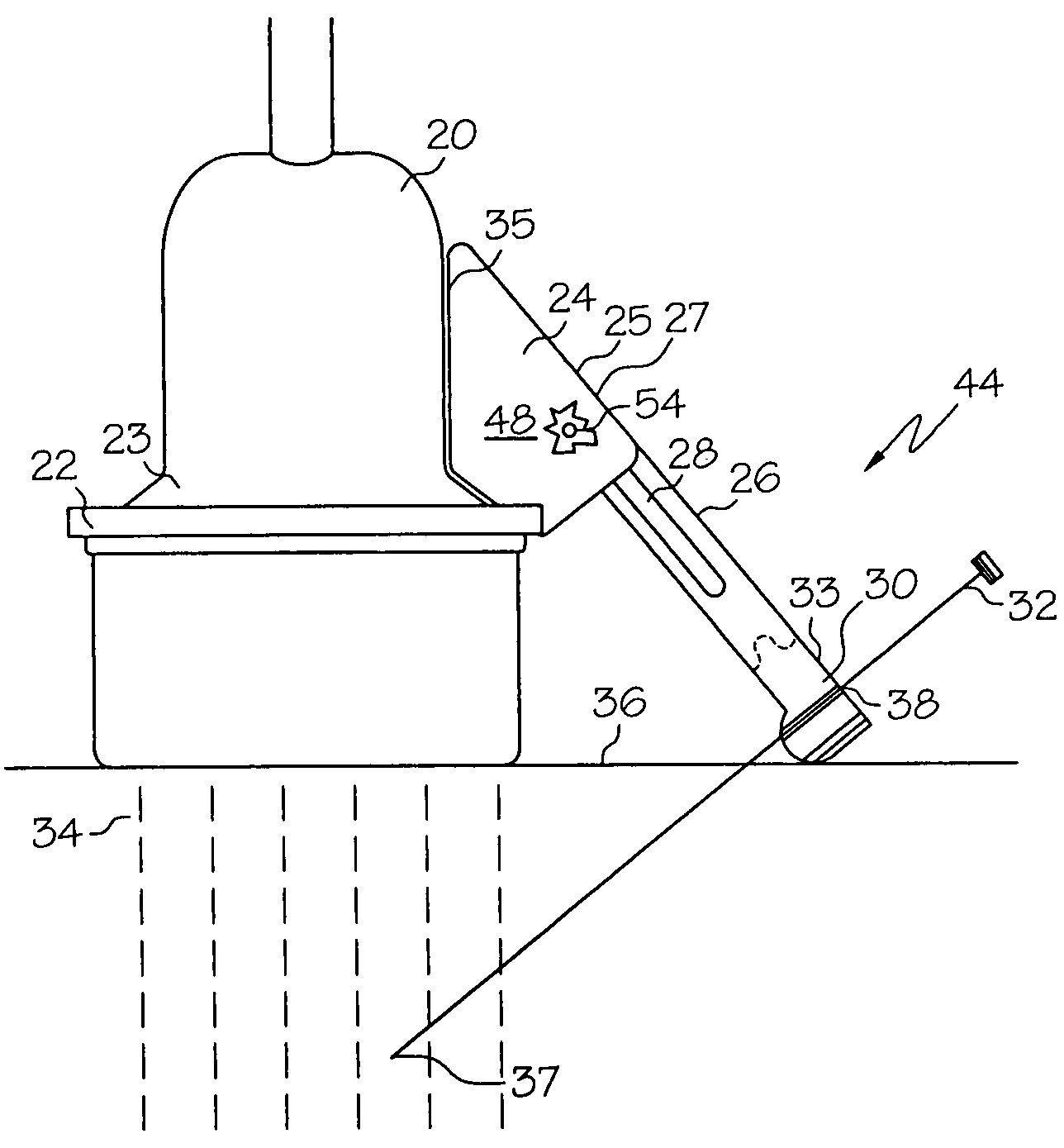
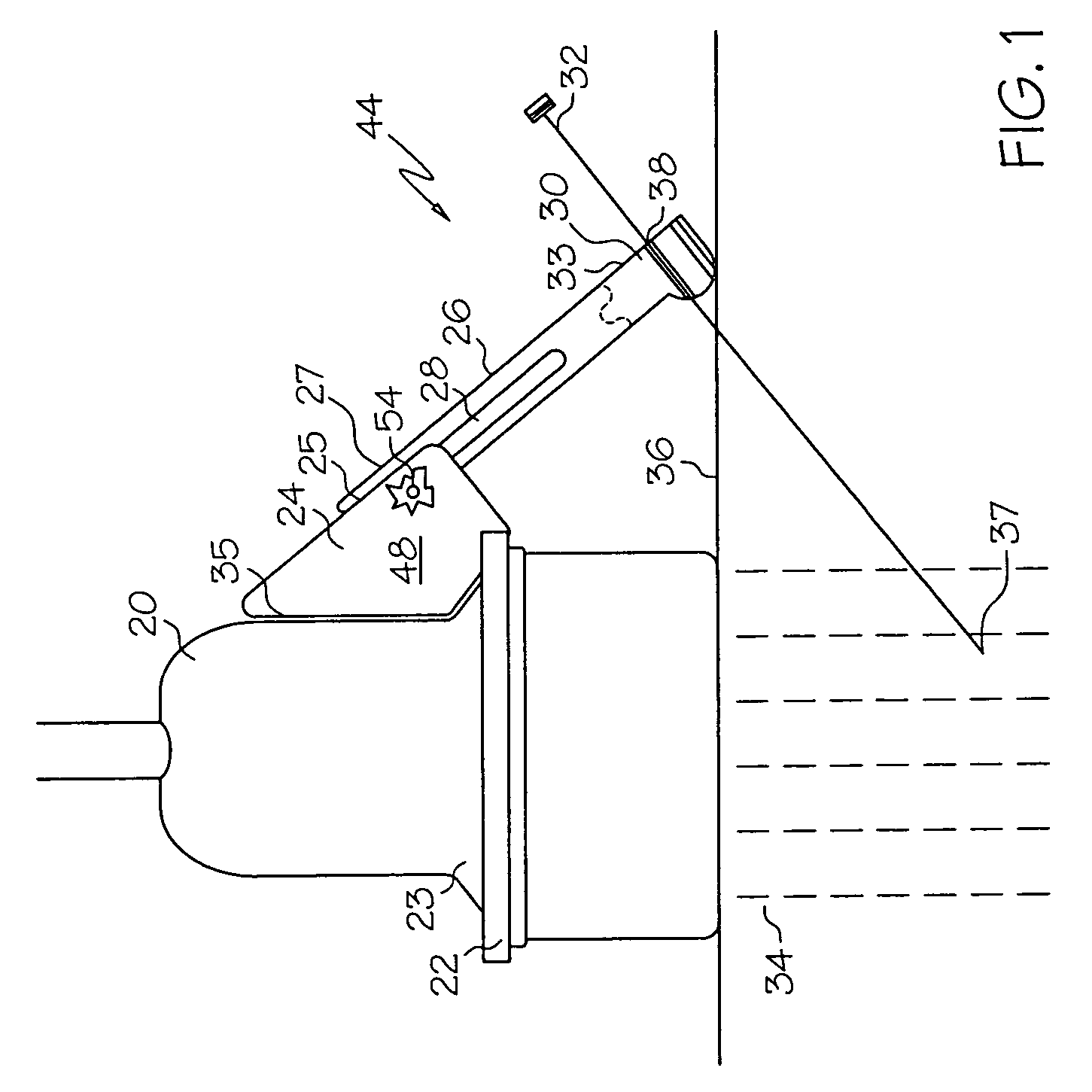
[0026]As indicated in the drawings, the present invention is directed to needle guide systems. Advantageously, the needle guide system of the present invention is adapted to properly position a needle within a narrow imaging beam of an imaging device. In one embodiment, the needle guide system allows such proper positioning while maintaining independent adjustment of the imaging device relative to the needle guide system. Methods in accordance with the present invention are directed to positioning a needle relative to an imaging device.

[0027]As used herein, “body” is intended to refer to an individual on whom a procedure is performed. As used herein, “individual” is intended to refer to animals, including but not limited to humans, mammals, and rodents. As used herein, “predetermined orientation” is intended to refer to a position or alignment of the arm and / or needle guide with respect to an imaging device before, during, or after a needle is inserted into the body. As used herein,...


PUM


Abstract

A needle guide system comprises a base adapted for non-pivotal connection to an imaging device, an arm pivotally connected to the base, and a needle guide pivotally connected to the arm at a point distal from the arm-base connection. The needle guide is adapted to receive at least one needle. The length of the arm extending between the base and the needle guide is adjustable. Methods for positioning a needle relative to an imaging device employ the needle guide system.

Description

FIELD OF THE INVENTION[0001]The present invention relates to medical devices and more particularly to needle guide systems and methods for positioning a needle relative to an imaging device.BACKGROUND OF THE INVENTION[0002]Imaging devices provide images which assist medical practitioners in positioning a needle to perform a wide range of procedures. These include such procedures as drainage, precision injections, biopsies, and ultrasonic imaging in performing, for example, amniocentesis, cordocentesis and transabdominal chorionic villus sampling.[0003]While relatively broad, the imaging beam of such imaging devices is generally flat. To obtain a clear image of a needle as it is guided into a desired target area, it is often desirable for the needle to be positioned at an angle of approximately 45 degrees with respect to an axis of an imaging beam. However, it has often been difficult to maintain a needle within an imaging beam, particularly within the desired angle with respect to t...

Claims


Application Information

Patent Timeline
IPC IPC(8): A61B19/00A61B17/34
CPCA61B17/3403A61B2019/5276A61B2090/378
Inventor SONEK, JIRI D.
Owner SONEK JIRI D
Why Eureka
Try Eureka