Fixing device, fixing method and image forming apparatus

a fixing device and image forming technology, applied in the direction of electrographic process apparatus, instruments, optics, etc., can solve the problems of increasing energy, insufficient gloss of images, and various problems of techniques described in the above literature, and achieve excellent image quality in the transparency of toner images and ohp permeability, simple apparatus construction, and high gloss

Inactive Publication Date: 2006-04-04
FUJIFILM BUSINESS INNOVATION CORP
View PDF22 Cites 8 Cited by
  • Summary
  • Abstract
  • Description
  • Claims
  • Application Information

AI Technical Summary

Benefits of technology

[0026]In the light of the foregoing, the present invention provides a fixing device, a fixing method and an image forming apparatus which are capable of, from the start, stably obtaining an image which has image quality excellent in transparency of a toner image and OHP permeability with a simple apparatus construction, and which has high glossiness and is free from gloss nonuniformity, without consuming useless energy and with which curl is hardly caused in a recording material.
[0027]In addition, the present invention provides a fixing device, a fixing method and an image forming apparatus which are capable of controlling glossiness of a fixed image up to desired glossiness.

Problems solved by technology

However, it is known that in the toner image 112 obtained from such a general fixing device, the glossiness of the image is insufficient.
However, the techniques described in the above literatures have various problems.
However, since plural fixing devices each including a heater are installed, the arrangement of the devices becomes complex, the heating energy is increased, and also since separation is carried out at a high temperature after the fixing, irregularities are generated on the image surface to cause an irregular reflection, and hence transparency of the toner is poor.
These points are problems.
Hence, there is a problem in that the apparatus becomes complicated, and since the recording material is heated and pressed twice, curl tends to be caused.
Hence, there is a problem in that essential properties of the recording material, e.g., a thickness, flexibility and the like are lost, and revision can not be made for the image formation surface, and further, when an OHP (overhead projector) film is used as the recording material, the whole transmittance is reduced (an OHP permeability is reduced).
In “a method in which belt fixing is adopted, and the cooling and peeling-off are carried out” of (5), there is a problem in that nonuniformity tends to occur in a degree of glossiness of the fixed output image.
Also, if for the purpose of enhancing the cooling effect for obtaining high glossiness, there is adopted such a construction that a period of time required for the cooling process is lengthened, and a distance from the heating color mixture process is increased, then an increased scale of the apparatus will be incurred.
In addition, since the fixing film cooled once needs to be heated up to a predetermined temperature again in a next cycle, the power consumption is large, and a period of time required for the heating is lengthened.

Method used


Image

  • Fixing device, fixing method and image forming apparatus
  • Fixing device, fixing method and image forming apparatus
  • Fixing device, fixing method and image forming apparatus

Examples


example 1

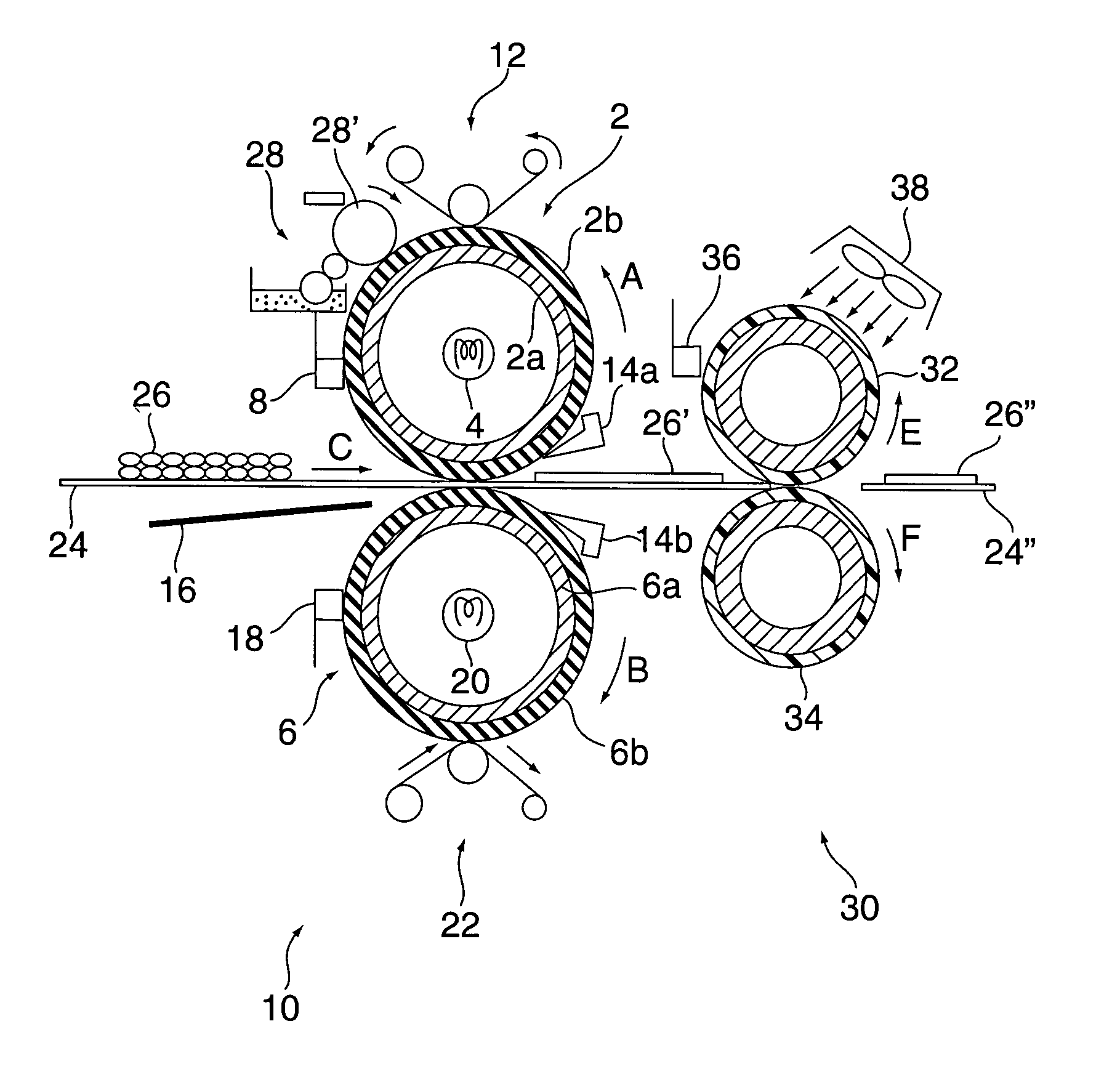
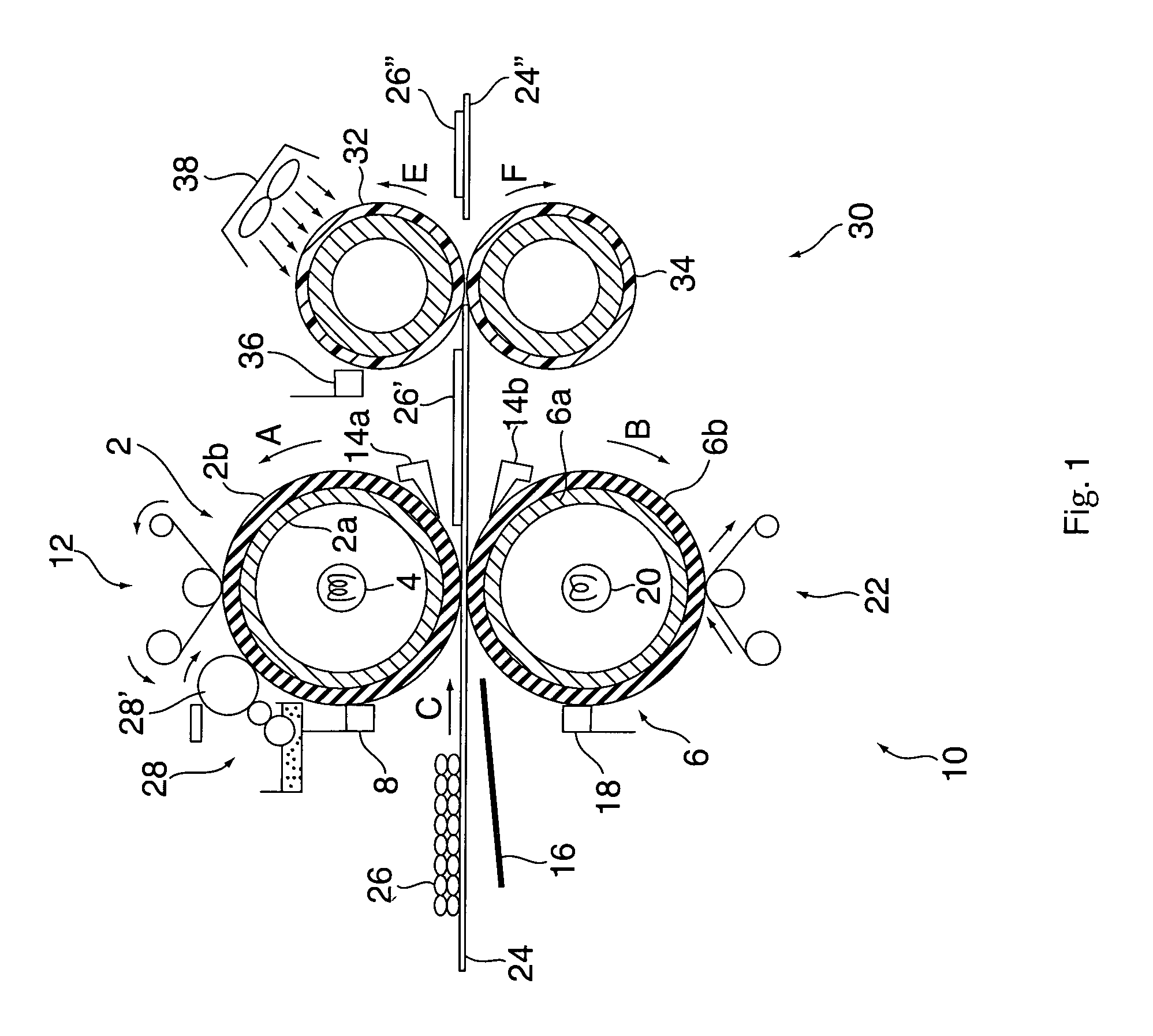
[0180]In Example 1, a fixing device having the same construction as that in Embodiment 1 described above, i.e., the construction shown in FIG. 1, was manufactured. The detailed specifications are as follows.

[0181](Heating and Temporarily Fixing Device 10)

[0182]The heating roll (heating rotating body) 2: Its diameter is 50 mm and its length is 350 mm. It is formed by coating a cylindrical substrate made of aluminum as the metal core 2a with a silicone rubber layer having a thickness of 3 mm and a high heat conductivity as the elastic body layer 2b.

[0183]The pressure roll (pressure rotating body) 6: Its diameter is 50 mm and its length is 350 mm. It is formed by coating a cylindrical substrate made of aluminum as the metal core 6a with a silicone rubber layer having a thickness of 1.5 mm and a high heat conductivity as the elastic body layer 6b.

[0184]The fixing nip portion between the heating roll 2 and the pressure roll 6: In the fixing nip portion formed between the heating roll 2...

example 2

[0208]In Example 2, a fixing device having the same construction as that in Embodiment 2 described above, i.e., the construction shown in FIG. 4, was manufactured. Example 2 is different from Example 1 only in the construction of the image gloss controller 50, and other constituent elements and set parameters thereof are the same as those in Example 1. The detailed specifications of the image gloss controller 50 are as follows.

[0209](Image Gloss Controller 50)

[0210]The distance between the heating and temporarily fixing device 10 and the image gloss controller 50: The image gloss controller 50 is arranged such that the head of the pressing nip portion between the gloss control belt 60 and the pressing control roll 54 is located at the position 42 mm behind the fixing nip portion between the heating roll 2 and the pressure control roll 6. It takes about 0.33 mm seconds to arrange the image gloss controller 50.

[0211]The gloss control belt 60: It is obtained by forming PFA with a 50 μm...

example 3

[0223]In Example 3, a fixing device having the same construction as that in Embodiment 3 described above, i.e., the construction shown in FIG. 8 was manufactured. Example 3 is different from Example 1 only in the construction of the image gloss controller 50, and other constituent elements and set parameters thereof are the same as those in Example 1. The detailed specifications of the image gloss controller 50 are as follows.

(Image Gloss Controller 70)

[0224]The distance between the heating and temporarily fixing device 10 and the image gloss controller 70: The image gloss controller 70 is arranged such that the head of the pressing nip portion between the gloss control roll 72 and the pressing control roll 34 is located at the position 42 mm behind the fixing nip portion between the heating roll 2 and the pressure control roll 6. It takes about 0.33 seconds to arrange the image gloss controller 70.

[0225]The gloss control roll 72: Its diameter is 30 mm. It is formed by covering the ...


PUM


Abstract

Provided is a fixing device and a fixing method, and an image forming apparatus using the fixing device, in which at least heat is applied to an unfixed toner image formed on a recording material to soften or melt toner of the unfixed toner image into a state of being able to be deformed by an external force, and while maintained in the state of being able to be deformed by the external force, the toner is pressed in a nonheating manner to be flowed. Accordingly, device structure can be simplified to be free of wasteful energy consumption, an image of image quality excellent in transparency of a toner image and in OHP permeability as well as of high glossiness which is free from gloss nonuniformity can be obtained while preventing curling of a recording material.

Description

FIELD OF THE INVENTION AND RELATED ART STATEMENT[0001]The present invention relates in general to a fixing device and a fixing method with which an unfixed toner image is fixed when forming an image using an apparatus for forming an image with toner such as a copying machine, a laser beam printer, a facsimile, a microfilm reader printer, or a recording machine, and to an image forming apparatus using the fixing device.[0002]More specifically, the invention relates to a fixing device and a fixing method of forming an unfixed toner image of an image pattern corresponding to objective image information on a surface of a recording material (such as an electrofacsimile sheet, an electrostatic recording sheet, a transferring material sheet or a printing paper) in accordance with a direct system or an indirect (transferring) system using toner made of a resin or the like having a heat melting property by an image forming process method such as an electrophotography, electrostatic recording...

Claims


Application Information

Patent Timeline
Patent Type & Authority Patents(United States)
IPC IPC(8): G03G15/20G03G15/00
CPCG03G15/2064G03G15/2021G03G15/6576G03G2215/00805
Inventor UEHARA, YASUHIROBABA, MOTOFUMI
Owner FUJIFILM BUSINESS INNOVATION CORP
Why Eureka
Try Eureka