
In-situ structural health monitoring, diagnostics and prognostics system utilizing thin piezoelectric sensors

a piezoelectric sensor and health monitoring technology, applied in the direction of instruments, mechanical measuring arrangements, mechanical roughness/irregularity measurements, etc., can solve the problems of large volume of ultrasonic sensors, and high cos

Inactive Publication Date: 2006-04-04
SOUTH CAROLINA UNIV OF
View PDF8 Cites 63 Cited by
  • Summary
  • Abstract
  • Description
  • Claims
  • Application Information

AI Technical Summary

Problems solved by technology

Ultrasonic sensors, which are relatively bulky and expensive, are typically used in portable devices placed in communication with the structure of interest so that the crystals propagate ultrasonic waves into the material.

Method used


Image

  • In-situ structural health monitoring, diagnostics and prognostics system utilizing thin piezoelectric sensors
  • In-situ structural health monitoring, diagnostics and prognostics system utilizing thin piezoelectric sensors
  • In-situ structural health monitoring, diagnostics and prognostics system utilizing thin piezoelectric sensors

Examples


Embodiment Construction

[0022]Reference will now be made in detail to presently preferred embodiments of the invention, one or more examples of which are illustrated in the accompanying drawings. Each example is provided by way of explanation of the invention, not limitation of the invention. In fact, it will be apparent to those skilled in the art that modifications and variations can be made in the present invention without departing from the scope or spirit thereof. For instance, features illustrated or described as part of one embodiment may be used on another embodiment to yield a still further embodiment. Thus, it is intended that the present invention covers such modifications and variations as come within the scope of the appended claims and their equivalents.

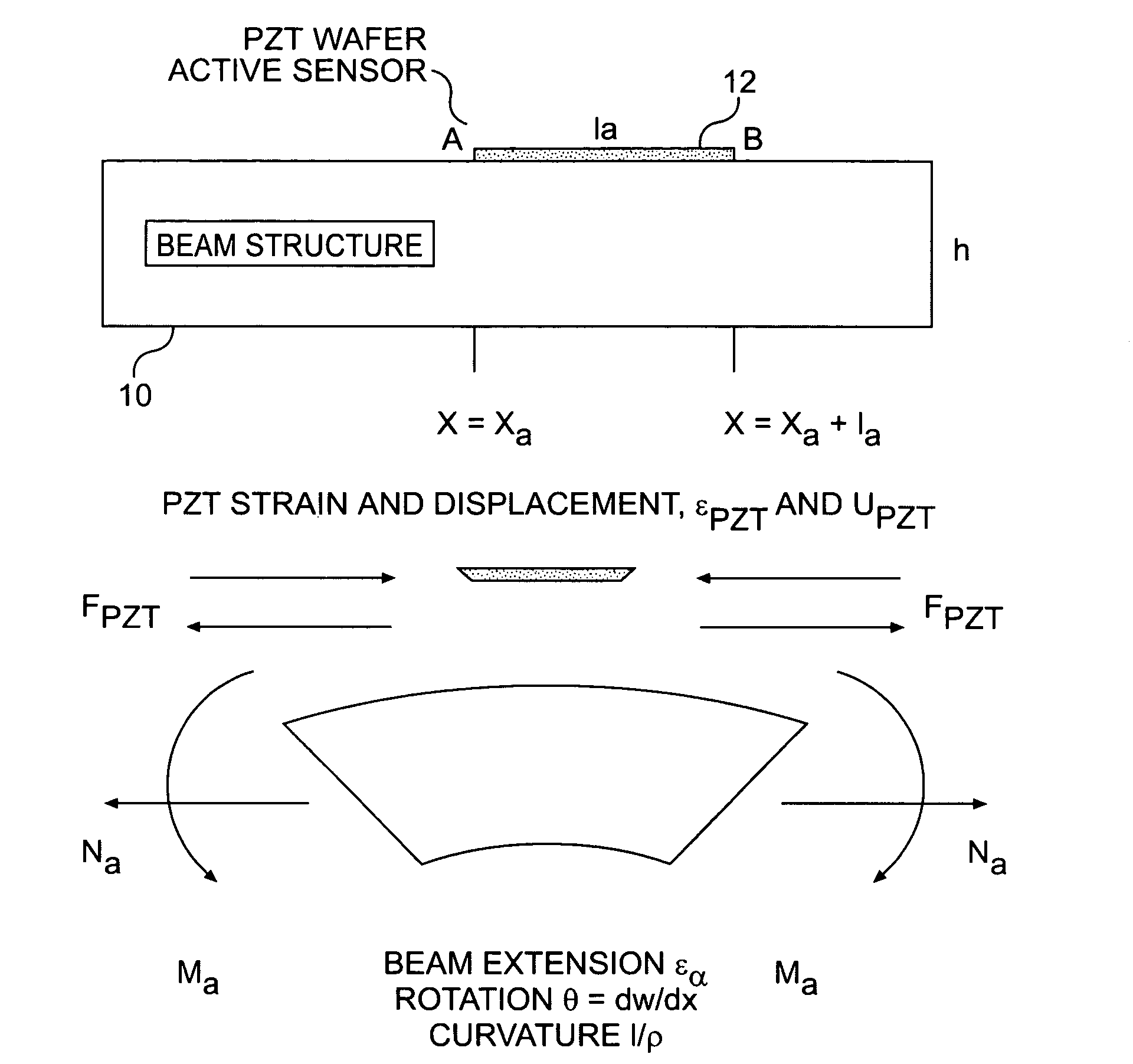
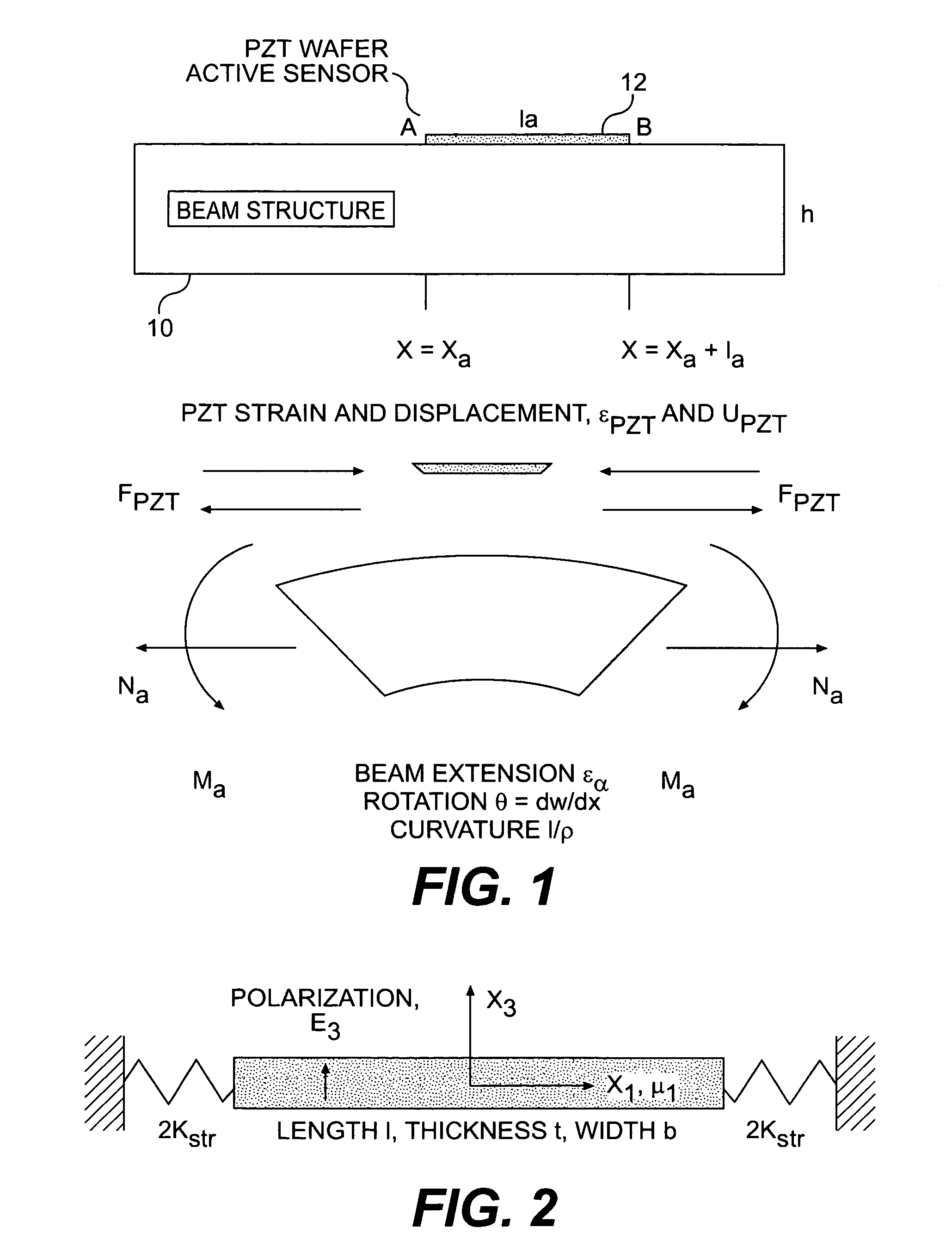
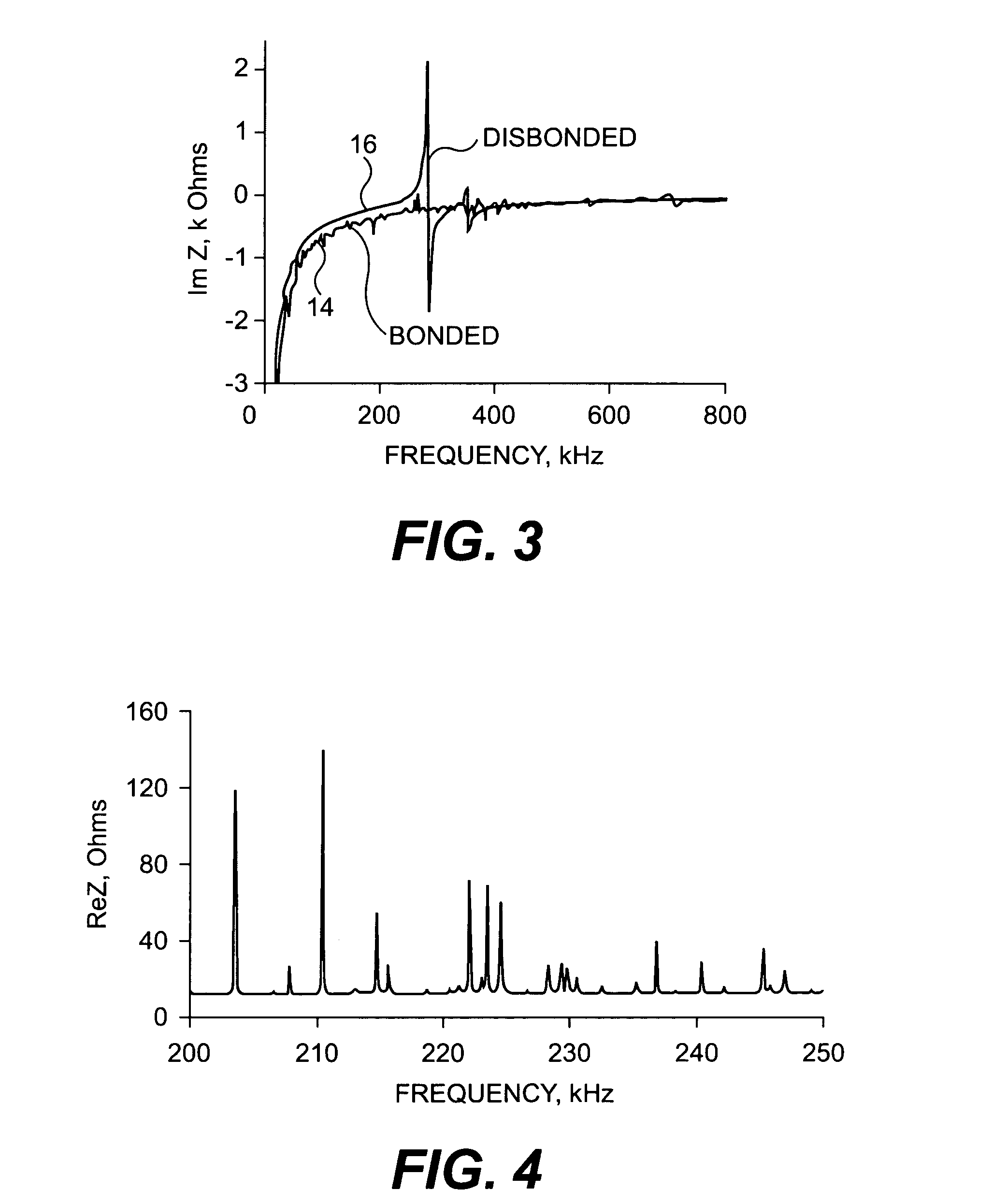
[0023]Generally, the present invention relates to embedding relatively small transducers on a structure in order to monitor the structure's structural health. Several examples are provided, namely, active electromechanical impedance sensing, a...


PUM


Abstract

A method of detecting a damaged feature within a structure includes embedding a plurality of thin piezoelectric ceramic sensors on the structure. A first sensor is excited so that the first sensor produces a responsive signal in the structure. The responsive signal is received at a second sensor. The presence or absence in the received responsive signal of at least one predetermined signal characteristic is determined, where the predetermined signal characteristic is related to existence of the damage feature.

Description

[0001]This application claims the benefit of U.S. Provisional Application No. 60 / 267,650, filed Feb. 8, 2001 and entitled “In-situ Structural Health Monitoring, Diagnostics and Prognostics System Utilizing Smart Active Sensors with Embedded Intelligence and Wireless Installation,” the entire disclosure of which is incorporated by reference herein.BACKGROUND OF THE INVENTION[0002]It has been recognized that there is a need to monitor the existence and effects of damage and corrosion in structural materials. Aircraft components provide a much publicized example, but the need exists in a variety of other structures, for example pipelines and building members. To detect defects, traditional modal analysis testing generally relies on structural excitation and vibration pickups. Structural excitation methods, in turn, usually employ either harmonic sweep or impulse excitation. The former method is more precise and can focus on resonant frequencies, while the latter is more expedient. Vibr...

Claims


Application Information

Patent Timeline
IPC IPC(8): G01B3/00B64D45/00G01N3/00G01N3/06G01N29/11G01N29/46
CPCG01N29/11G01N29/2437G01N29/2475G01N29/2493G01N29/46G01N2291/2694G01N2203/0623G01N2291/0231G01N2291/0258G01N2291/0427G01N2291/106G01N2203/0073
Inventor GIURGIUTIU, VICTOR
Owner SOUTH CAROLINA UNIV OF
Learn More