

Method for operating a cryocooler using on line contaminant monitoring
a technology of contaminant monitoring and cryocooler, which is applied in the field of low temperature or cryogenic refrigeration, can solve the problems of severe consequences of failure of cryocooler for such application systems
- Summary
- Abstract
- Description
- Claims
- Application Information
AI Technical Summary
Benefits of technology
Problems solved by technology
Method used
Image

Examples
casei
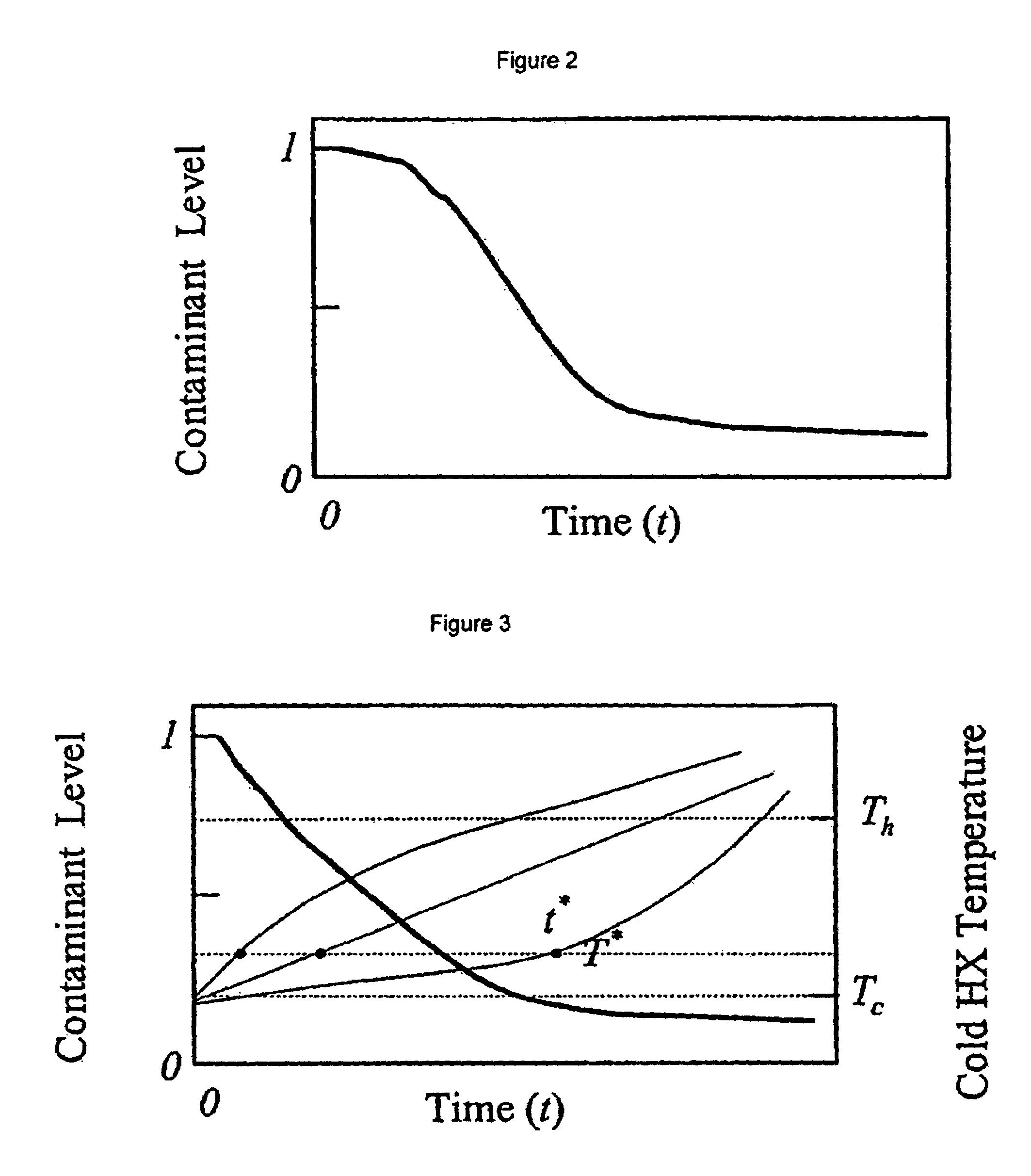
[0035]CaseI:ⅆCⅆt=0
[0036]CaseII:ⅆCⅆt<0
[0037]CaseIII:ⅆCⅆt>0
[0038]For case I, almost all the contaminants are already frozen and thus this cryocooler is expected to perform for an indefinite amount of time. For case II, contaminants are still being frozen thus it is expected that the cryocooler performance would further deteriorate. For case III, there is new contamination being introduced to the cryocooler, and the cryocooler should be serviced quickly.
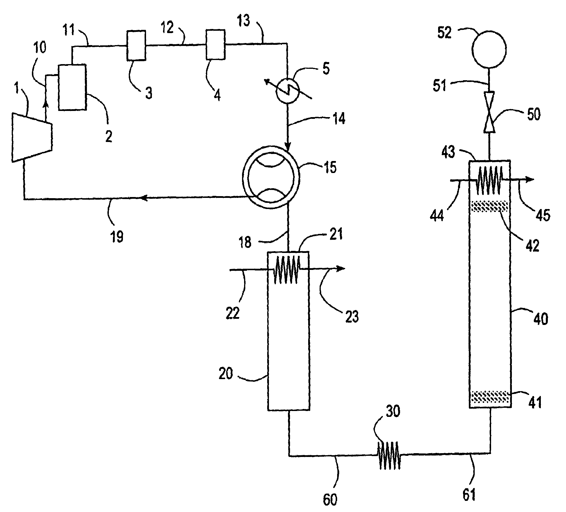
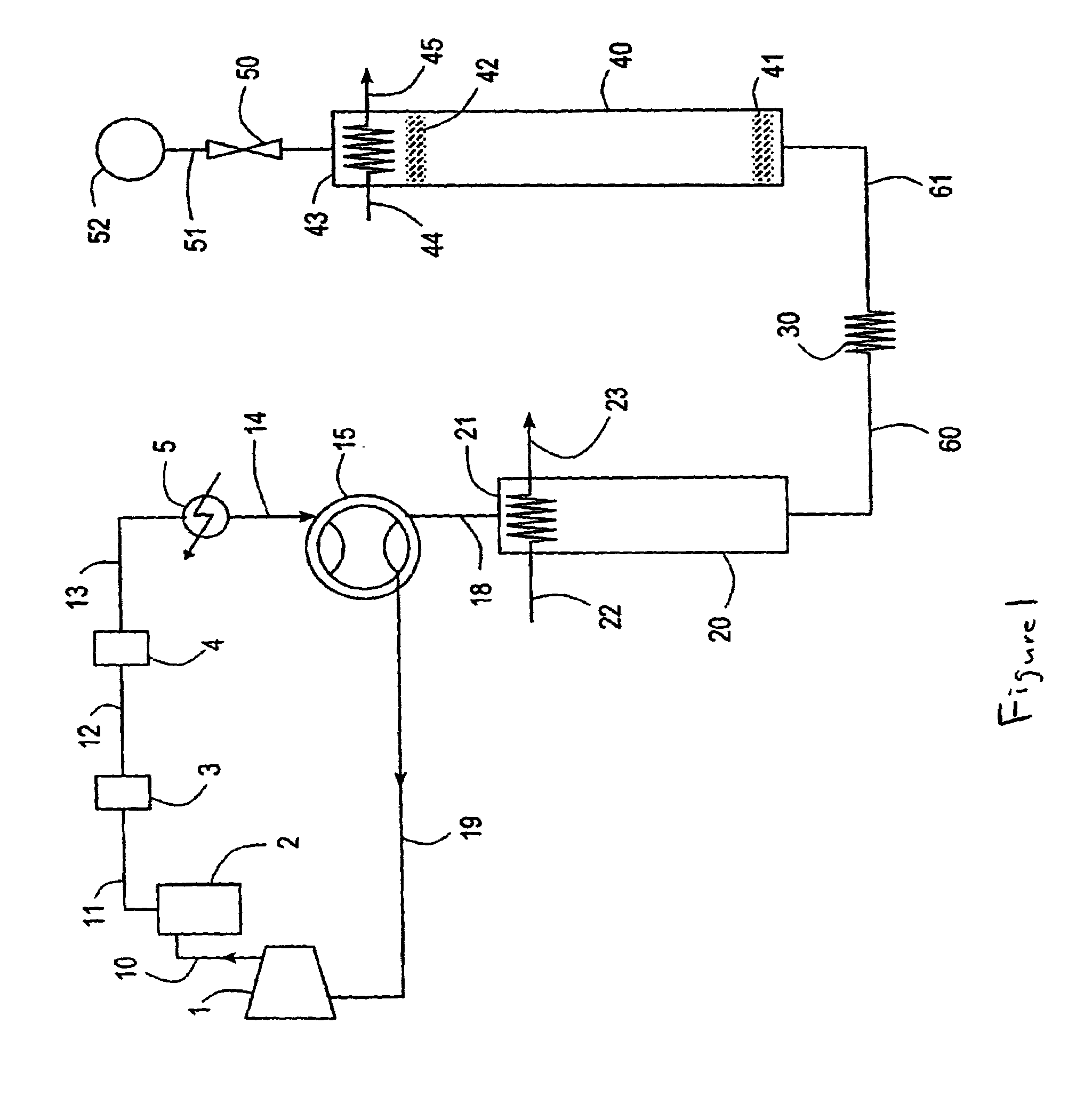
[0039]One of the main problems with the current cryocoolers driven by oil-flooded compressors is the failure of the oil separation system. If oil as in particulate or hydrocarbon vapor form passes the oil separation system, then the contaminant level increases or stays in a high level as shown below in FIG. 4. If a contaminant broke through the system and is still being introduced the contaminant level graph may show the following trends where additional contaminant is introduced into the system at time t1 and eithe...
PUM
| Property | Measurement | Unit |
|---|---|---|
| operating frequency | aaaaa | aaaaa |
| operating frequency | aaaaa | aaaaa |
| operating frequency | aaaaa | aaaaa |
Abstract
Description
Claims
Application Information