Electronic soap dispenser

a soap dispenser and electronic technology, applied in the direction of liquid transfer devices, instruments, volume meters, etc., can solve the problems of increased risk of damage or destruction to the soap dispenser, inability to match the esthetics of the other plumbing devices, and inability to operate manually

Active Publication Date: 2006-04-11
SLOAN VALVE COMPANY
View PDF22 Cites 44 Cited by
  • Summary
  • Abstract
  • Description
  • Claims
  • Application Information

AI Technical Summary

Benefits of technology

[0007]Accordingly, it is a general object of the present invention to provide a new and improved liquid soap dispenser.
[0008]Another object of the present invention is to provide a liquid soap dispenser with greater durability.
[0009]Yet another object of the present invention is to provide a liquid soap dispenser that complements other adjacently located plumbing fixtures, such as electronic faucets.
[0010]A further object of the present invention is to provide a smooth and continuous pathway for the soap delivery tube from a soap reservoir of a liquid soap dispenser.
[0011]A still further object of the present invention is to provide a liquid soap dispenser with a metal housing to improve resistance to vandalism of the like.

Problems solved by technology

Additionally, such manually-operated liquid soap dispensers do not match the esthetics of the other plumbing devices.
However, such soap dispensers are frequently located in public buildings where there is an increased risk of damage or destruction to the soap dispenser, such as due to vandalism.
Vandalism can be a significant problem in public buildings, especially in generally isolated areas such as is often the case with restrooms.
However, neither of these design patents discloses any internal structure, such as how the housing of the electronic liquid soap dispenser mates with the soap dispensing apparatus.

Method used


Image

  • Electronic soap dispenser
  • Electronic soap dispenser
  • Electronic soap dispenser

Examples


Embodiment Construction

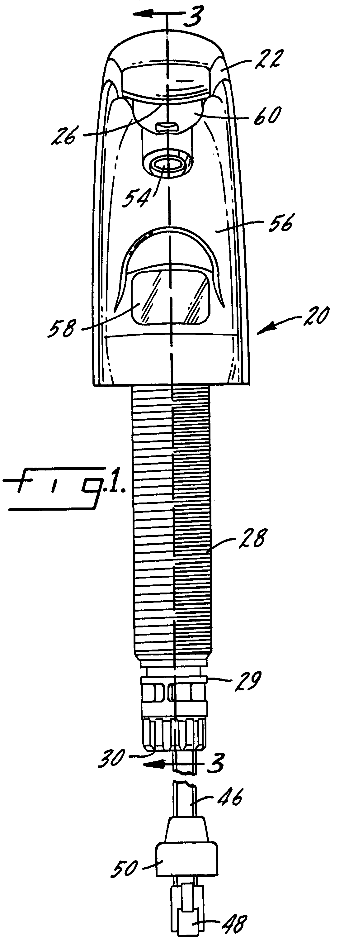
[0028]The present invention of an electronic soap dispenser, generally designated 20, to dispense liquid soap is shown in FIG. 1.

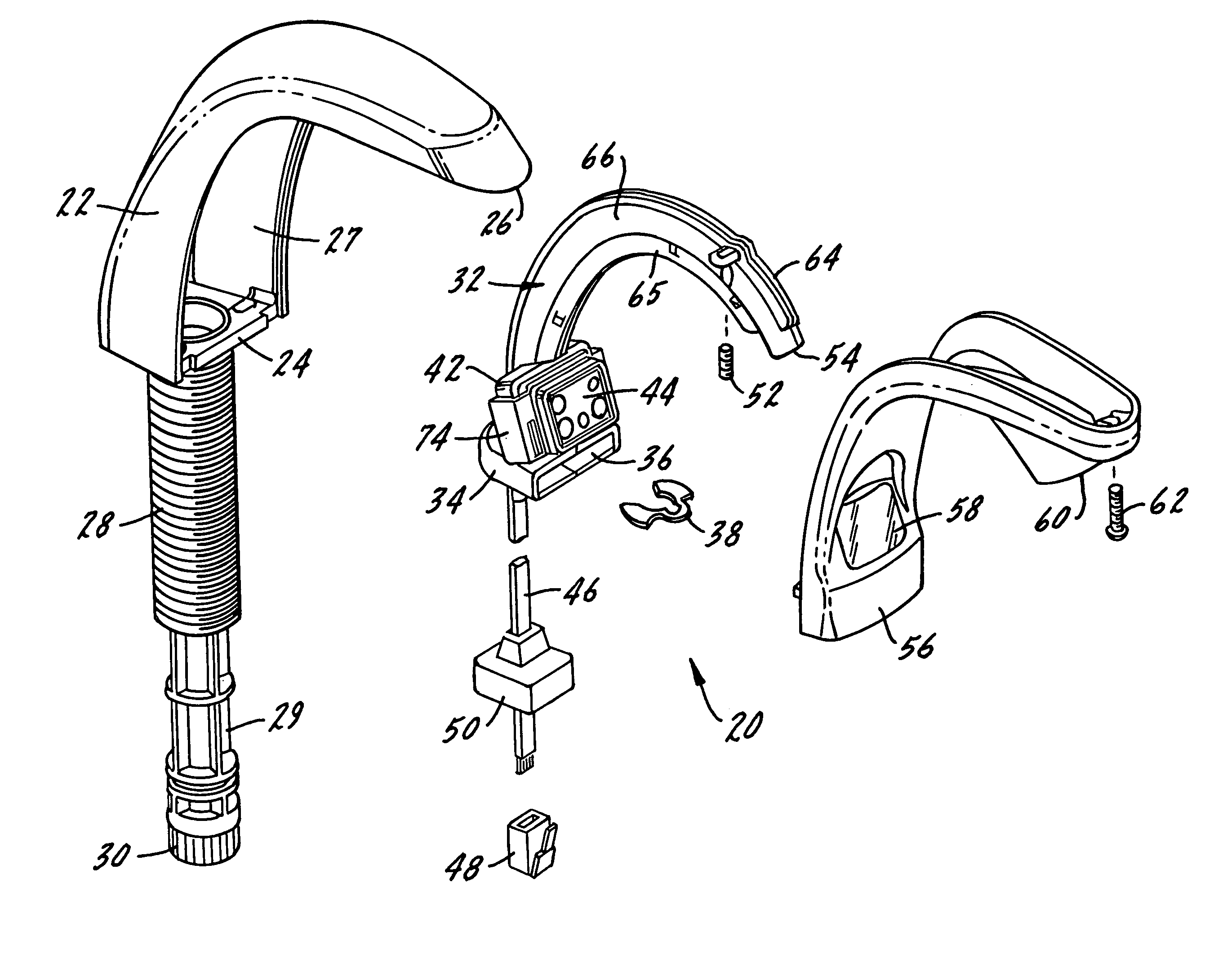
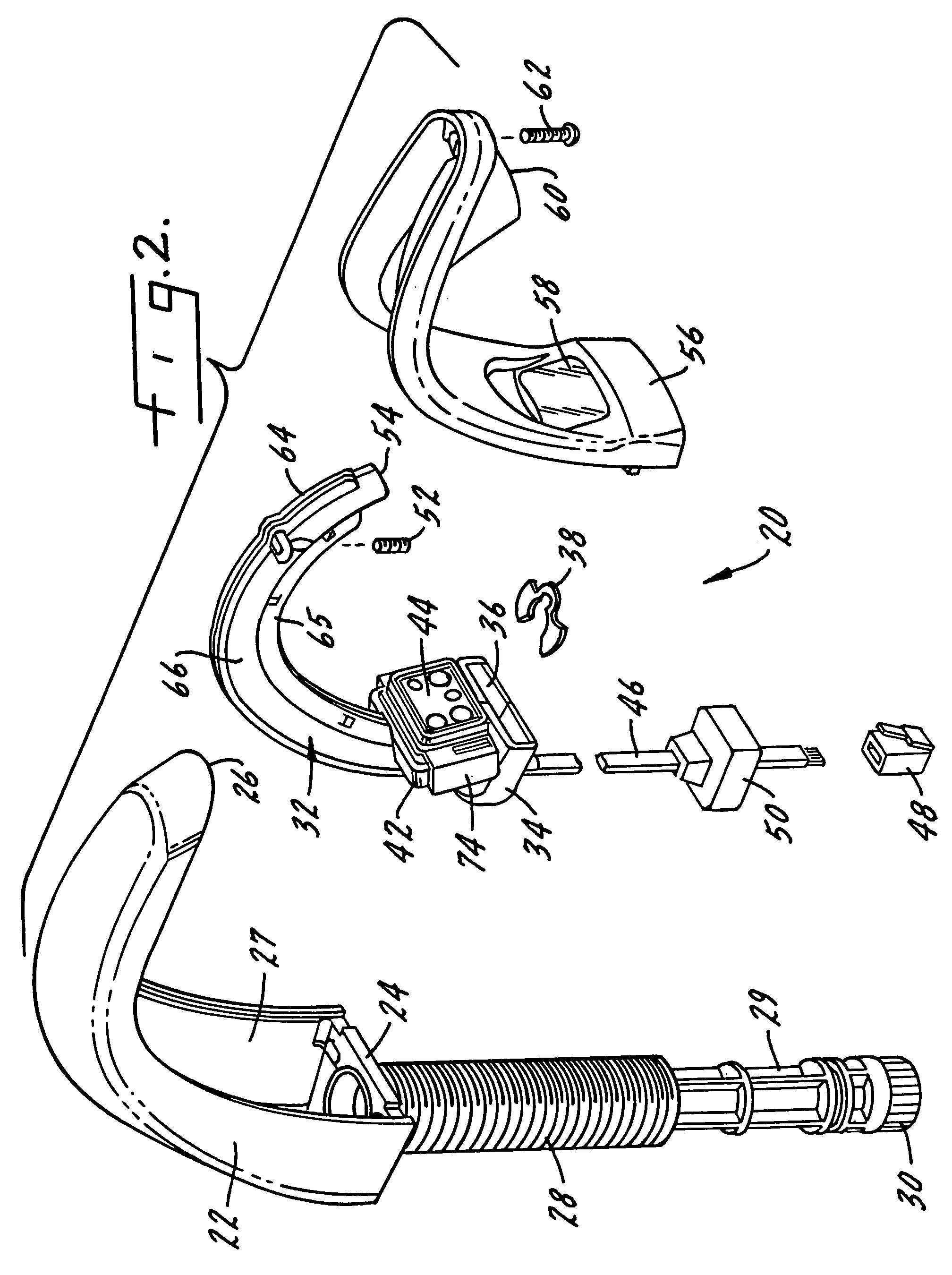
[0029]As can be seen in the exploded view of FIG. 2, soap dispenser 20 consists of a plurality of cooperating parts or components. A spout housing 22 is of generally curved or arcuate shape extending from a base 24 to a frontal edge 26 that extends above and forwardly with respect to the base 24. Spout housing 22 has a generally open front that defines an internal cavity 27. A threaded shank 28 engages corresponding threads in the base 24 of spout housing 22, for attachment of the spout assembly 20 to a sink or the like, such as with a threaded nut from the underside of the sink in a manner known to the art. A shank adapter 29 is received in the shank 28. A lower end 30 of shank adapter 29 is suited for receiving and holding a reservoir of liquid soap, such as a reservoir 40 shown in FIG. 4.

[0030]A soap path retainer 32 has a generally semicircular base po...


PUM


Abstract

A liquid soap dispenser includes a housing, a shank that engages a base of the housing, a soap path retainer disposed in the interior of the housing, a shank adapter disposed in the shank, and an infrared sensor to sense the presence of a user. A generally continuous passageway is defined through the shank adapter and the soap path retainer such that an elongated soap delivery tube of a liquid soap reservoir may be inserted through the passageway from the bottom of the soap dispenser to the spout end. The reservoir may be attached to the bottom end of the shank adapter. The soap path retainer is preferably formed of complementary halves, such as by plastic injection molding, that mate together to provide a curved passageway from near the base of the housing to the soap dispensing end and to support the sensor assembly.

Description

FIELD OF THE INVENTION[0001]The present invention relates generally to the field of electronic plumbing devices. More particularly, the present invention relates to apparatus for electronically dispensing liquid soap.BACKGROUND OF THE INVENTION[0002]Electronic faucets are known to the prior art that sense the presence of a person to initiate the flow of water, such as when a user's hands are placed under the faucet. Such electronic faucets are especially popular in public buildings and in health institutions because users do not have to come into contact with the faucet to activate the flow of water. There is therefore less likelihood that bacteria will be transferred between users of the faucet.[0003]Various types of manually-operated liquid soap dispensers also exist in the prior art. Since such manually-operated dispensers require physical contact with the dispenser, such as by actuating an internal manual pump, multiple users come into contact with the dispenser. Additionally, s...

Claims


Application Information

Patent Timeline
Patent Type & Authority Patents(United States)
IPC IPC(8): B67D5/08B67D7/00A47K5/12
CPCA47K5/1217A47K2005/1218
Inventor OLIVER, STEVEN R.NORTIER, RICHARD A.
Owner SLOAN VALVE COMPANY
Why Eureka
Try Eureka