
Green emitting phosphor material and plasma display panel using the same

a technology of green emitting phosphor and plasma display panel, which is applied in the direction of instruments, optical elements, gas-filled discharge tubes, etc., can solve the problems of limited number of lamp phosphors suitable for pdp applications, limited number of lamp phosphors, and less power of crt, so as to improve the probability of electron and hole capture to the impurity, the effect of enhancing the recombination rate and minimizing the potential for cross contamination

Inactive Publication Date: 2006-04-11
PANASONIC CORP
View PDF11 Cites 4 Cited by
  • Summary
  • Abstract
  • Description
  • Claims
  • Application Information

AI Technical Summary

Benefits of technology

[0017]Phosphor materials are extremely sensitive to impurities, even at ppb levels. The low-temperature process minimizes the potential for cross contamination. Some of the unwanted impurities left in the materials from high temperature calcination may pose a threat to the performance of a phosphor. As the size of the phosphor particle decreases, the probability of electron and hole capture to the impurity increases and the e–h localization enhances the recombination rate via the impurity. The optimum impurity concentration (activator) level can be further increased with small particle size. This can be achieved by starting with sub micron size starting chemicals or sol gel process.

Problems solved by technology

Although, CRT works with less power and having better picture quality, it has size limitation.
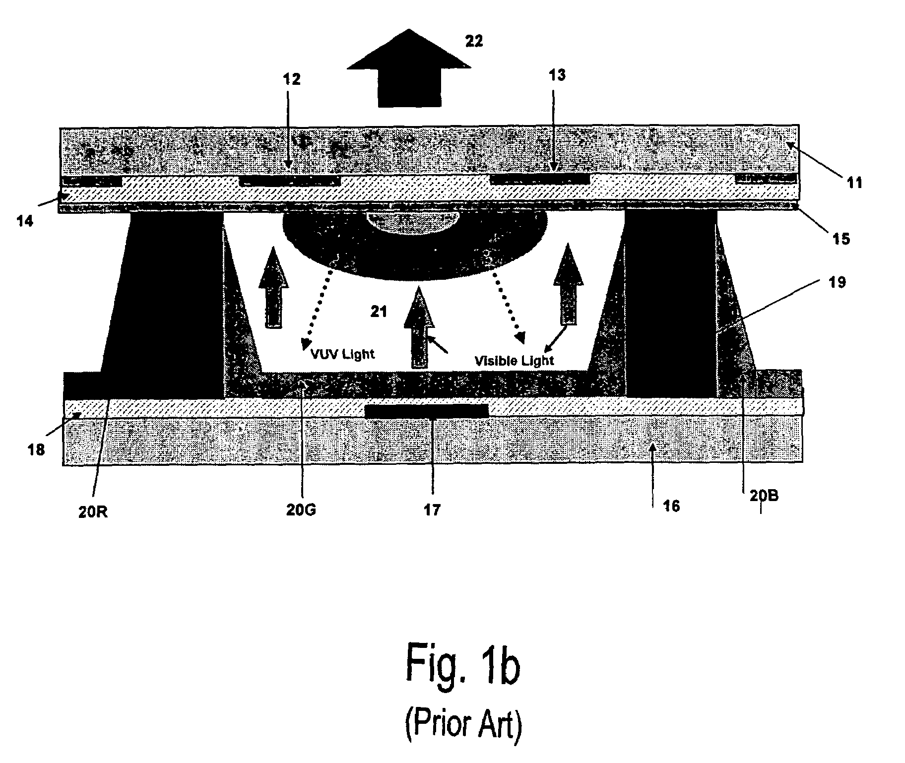
Due to vacuum UV specific wavelengths available from Xe discharge (147 nm and 173 nm), only a limited number of lamp phosphors are suitable for PDP applications.
This results in compromises in the performance of the display.

Method used


Image

  • Green emitting phosphor material and plasma display panel using the same
  • Green emitting phosphor material and plasma display panel using the same
  • Green emitting phosphor material and plasma display panel using the same

Examples


example i

[0071]The preparation of Mn and Li activated lanthanum aluminate phosphor by a solid-state reaction is described in this example.

[0072]First, 28 grams of gamma (80–95%)—alpha (5–20%) aluminum oxide (0.01 to 0.02 micron powder), 18 grams of lanthanum oxalate, 0.34 grams of manganese fluoride (II), 1 gram of lithium fluoride are mixed in a mortar and pestle and transferred to high grade alumina crucible. The crucible is covered with lid and calcined at 1200 to 1400° C. for 2 to 4 hours in a box furnace. Samples are re-fired in a forming gas (4.5% H2+95.5% N2) at 1100 to 1300° C. for 2 to 4 hours in a tube furnace. The sample is left in the furnace in presence of forming gas until it cools down to room temperature.

[0073]After cooling, these fine phosphor powders are subjected to ultrasonic agitation in water. Ultrasonic treatment helps to break the clusters into individual particles. After washing with water, these powders are dried at 120° C. for 6 hours.

[0074]Depending on the require...

example ii

[0075]The preparation procedure is the same as in example I except 0.34 grams of manganese fluoride (II) is replaced by 0.42 grams of manganese carbonate.

example iii

[0076]The preparation procedure is the same as in example I except 0.34 grams of manganese fluoride is replaced by 0.65 grams of manganese nitrate.


PUM

PropertyMeasurementUnit
temperatureaaaaaaaaaa
particle sizeaaaaaaaaaa

Abstract

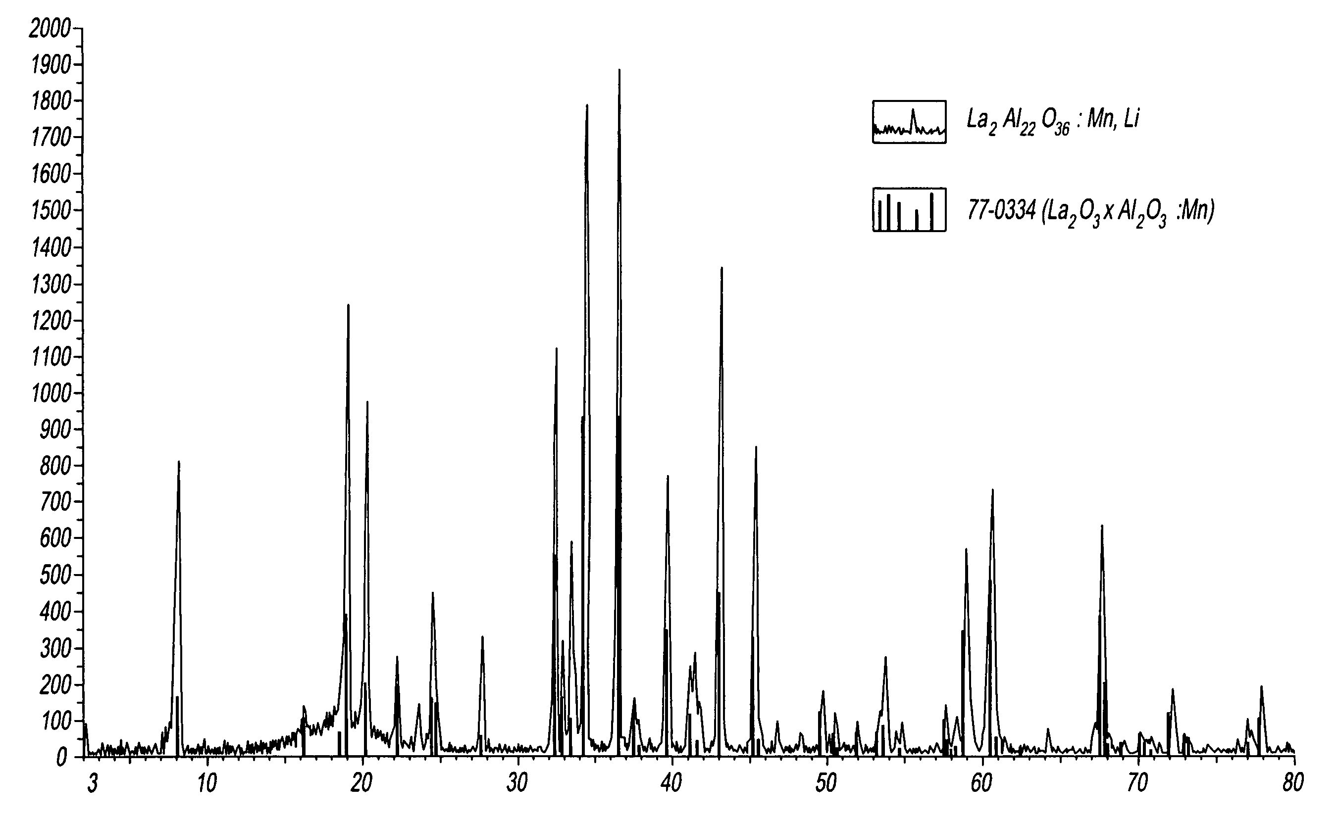
A green emitting lanthanum aluminate phosphors activated with manganese and alkali for plasma display panels (PDP) having an empirical formula:La2−x−y−B22O36:Mnx.Aywherein: A=Li, Na or K; B=Al or Al+Ga; and 0.01≦x≦0.1 and 0.01≦y≦0.1 is provided. The phosphor has a band emission in green region, peaking at 515 nm when excited by 147 and 173 nm radiation from Xenon gas mixture, a uniform particle size distribution (0.01 to 10 microns), which is a size distribution appropriate for thin phosphor screens required for a variety of flat panel display and lamp applications. They exhibit high brightness, good color saturation, good stability and shorter persistence under VUV excitation.

Description

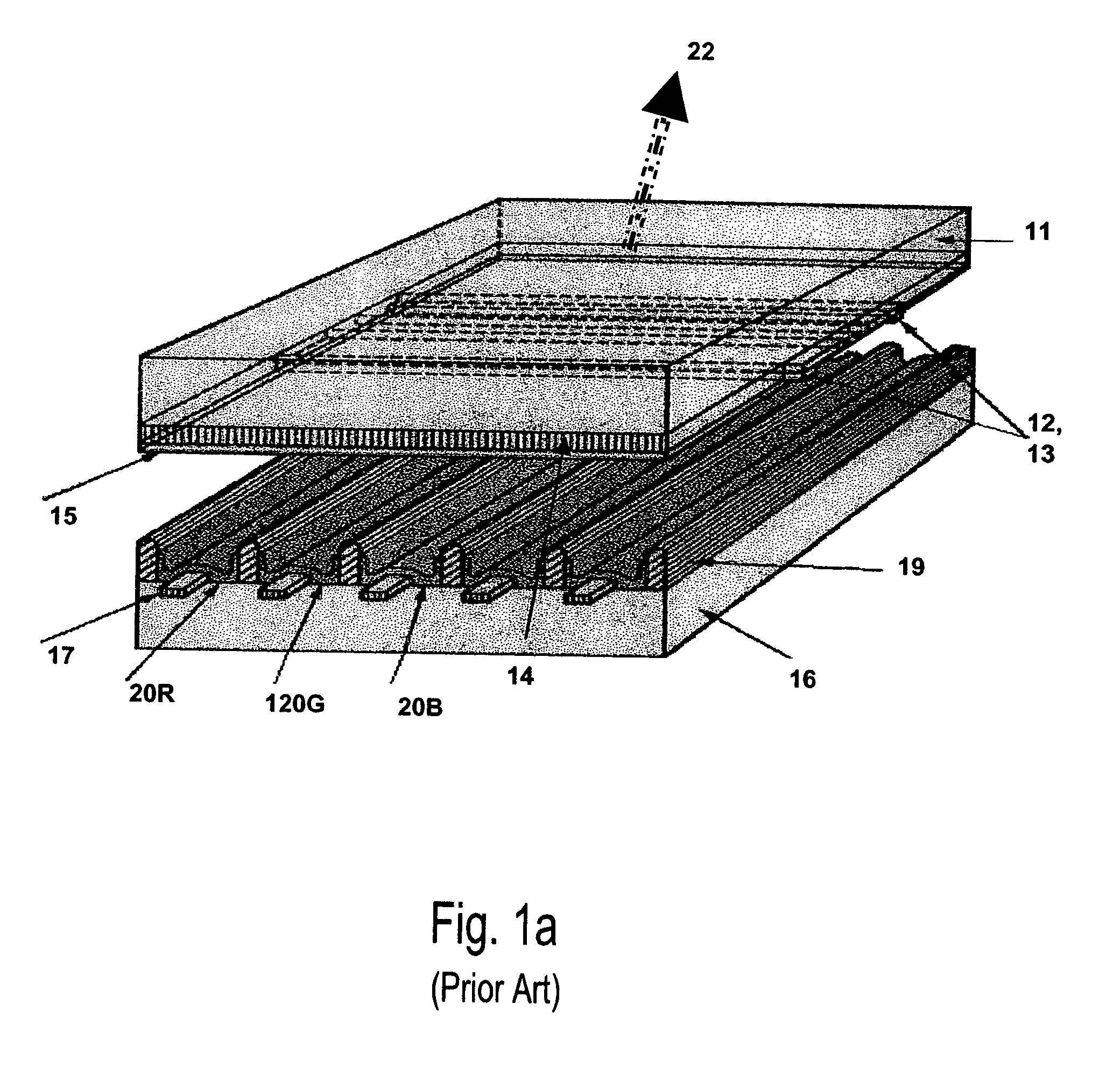
BACKGROUND OF THE INVENTION[0001]1. Field of the Invention[0002]The present invention relates to the preparation and growth of small size particles Mn2+ and alkali doped lanthanum aluminate phosphor by solid state and sol-gel methods. More specifically, the present invention provides green emitting Mn2+ and alkali doped lanthanum aluminate phosphor and process by thermally decomposing salts of lanthanum, manganese, alkali and alumina or sol-gel powders.[0003]2. Description of the Related Art[0004]The plasma display panel (PDP) as a medium of large format (60+″) television (TV), particularly high definition TVs (HDTV's) is gaining attention over cathode ray tube (CRT) based TVs due to its' high performance and scalability. Although, CRT works with less power and having better picture quality, it has size limitation. Larger screens (CRT) of diagonal size more than 40 inches have larger depth and very heavy. Conversely, diagonal size of PDP is growing day by day, as there is no problem...

Claims


Application Information

Patent Timeline
Patent Type & Authority Patents(United States)
IPC IPC(8): C09K11/80C09K11/08
CPCH01J11/42C09K11/7706C09K11/77C09K11/63
Inventor RAVILISETTY, PADMANABHA RAO
Owner PANASONIC CORP
Learn More