Multi-well container processing systems, system components, and related methods

a multi-well container and processing system technology, applied in chemical methods analysis, material testing goods, instruments, etc., can solve problems such as limiting assay throughput, and achieve the effect of minimizing the disruption of cells and minimizing the agitation of other materials

Inactive Publication Date: 2006-03-09
IRM
View PDF5 Cites 21 Cited by
  • Summary
  • Abstract
  • Description
  • Claims
  • Application Information

AI Technical Summary

Benefits of technology

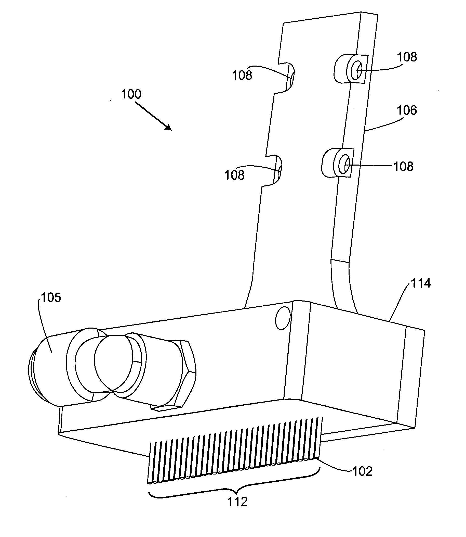
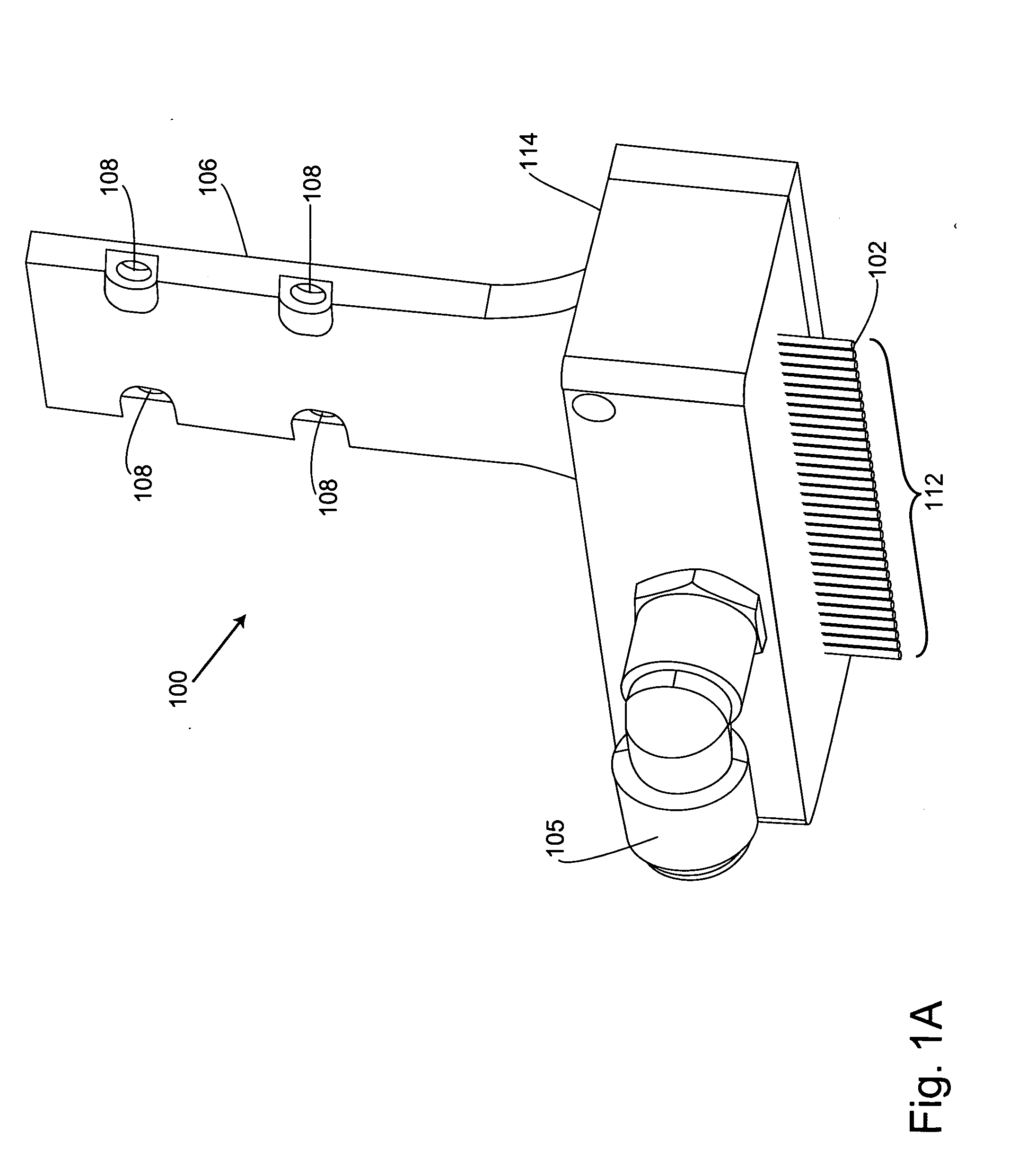
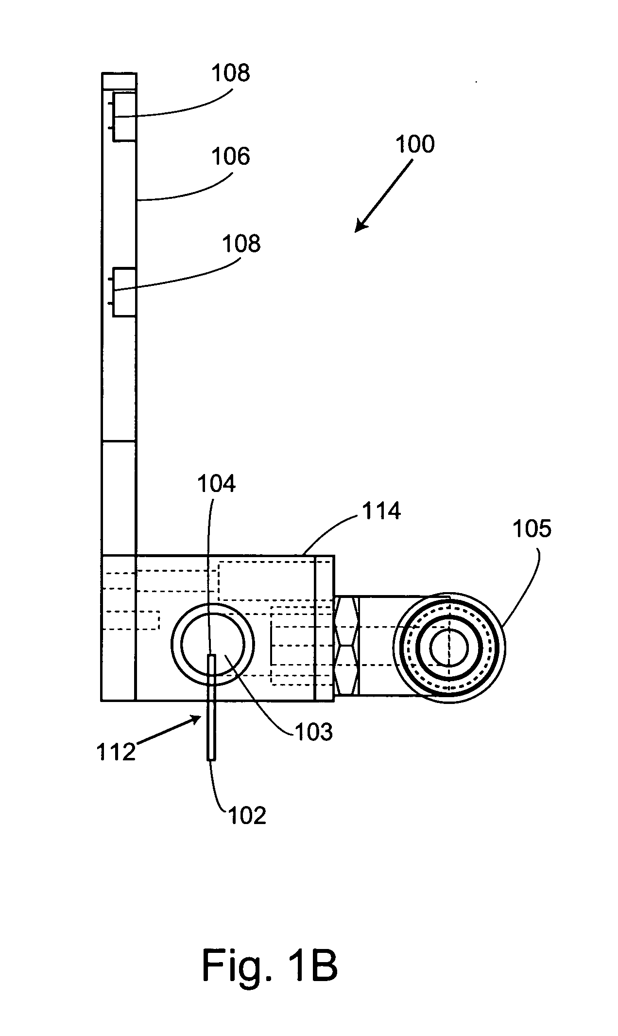
[0007] The present invention provides multi-well container processing systems and system components. For example, the invention provides fluid removal heads that can be used to remove fluidic materials from multi-well containers, such as micro-well plates, reaction blocks, and the like. The fluid removal heads of the invention include tips that are structured to minimize cross-contamination among wells when fluids are removed from the containers. Typically, these fluid removal heads are included as components of the systems of the invention. The systems described herein may be utilized to perform, e.g., well washing or cleaning steps, various assays, and other procedures with throughput that is superior to those processes performed using many pre-existing systems. The invention also provides methods of removing fluid from multi-well containers and kits that include the fluid removal heads described herein.
[0011] The tips utilized in the systems of the invention include various embodiments. In certain embodiments, for example, the inlet and the outlet communicate with each other via at least one channel disposed through the tip. The channel generally includes a cross-sectional dimension of 50 μm or more, e.g., to prevent cells and other materials in fluids from obstructing the channel when those fluids are removed from the wells of a multi-well container. When the tip is disposed in the well or proximal to the opening to the well, the space disposed between the outer surface of the tip and the sides of, and / or an opening to, the well includes a distance of 1 mm or less. Optionally, the tip includes a cross-sectional shape selected from, e.g., a regular n-sided polygon, an irregular n-sided polygon, a triangle, a square, a rectangle, a trapezoid, a circle, an oval, and the like. In some embodiments, at least one valve (e.g., a solenoid valve, etc.) fluidly communicates with the tip. The valve is generally structured to regulate pressure flow from the negative pressure source. In certain embodiments, for example, the valve is operably connected to the controller, which effects the regulation of the pressure flow.
[0012] In certain embodiments, a fluid removal head comprises the tip. In some embodiments, the fluid removal head includes at least one body structure. Optionally, a resilient coupling couples the tip to the body structure, e.g., to minimize damage to system components and multi-well containers if the tips inadvertently contact the multi-well containers during operation of the system. In certain embodiments, the body structure includes at least one manifold, e.g., such that fluids can be removed from multiple wells in a multi-well container substantially simultaneously. In some embodiments, the fluid removal head includes at least two tips that are spaced to simultaneously fit within a single well of a multi-well container, e.g., such that fluid can be removed from the well through both tips. Typically, the fluid removal head includes at least two tips that are spaced at a distance that substantially corresponds to a distance between at least two wells disposed in a multi-well container. To illustrate, the tips are optionally structured to remove fluids from multi-well containers that comprise 6, 12, 24, 48, 96, 192, 384, 768, 1536, or more wells. In some embodiments, the tip extends 0.1 mm or more into a cavity of a fluid removal head body structure, e.g., to prevent removed fluid from moving from the cavity back into the tip through the outlet. Optionally, the fluid removal head is structured to remove fluids from a plurality of multi-well containers substantially simultaneously.
[0015] To further illustrate, the system includes at least one dispensing component that is structured to dispense one or more fluids into one or more wells of one or more multi-well containers in some embodiments of the invention. In these embodiments, the dispensing component typically includes at least one dispenser that aligns with one or more wells disposed in one or more multi-well containers when the multi-well containers are disposed proximal to the dispenser. The dispenser is generally structured to dispense one or more fluids into the wells. In some embodiments, the dispenser is angled relative to a vertical axis of the wells, e.g., such that when fluids are dispensed from the dispenser they contact the sides of wells instead of directly contacting cells adhered at the bottoms of wells to minimize disruption of the cells. In some of these embodiments, the dispensing component is structured to dispense the fluids into a plurality of multi-well containers substantially simultaneously.
[0016] In still another aspect, the invention relates to a method of removing fluid from a well of multi-well container. The method includes a) providing at least one tip that comprises at least one inlet and at least one outlet, which inlet communicates with the outlet, in which the tip has a cross-sectional dimension that is smaller that a cross-sectional dimension of the well thereby forming a vent opening in a space disposed between the tip and sides of, and / or an opening to, the well when the tip is positioned in the well or proximal to the opening to the well. The method also includes b) lowering the tip to a first position in the well, which first position is below a surface of the fluid, while applying a first negative pressure to the tip, in which the tip is lowered at a rate that is faster than the fluid is removed from the well by the negative pressure, or lowering the tip to the first position in the well and then applying the first negative pressure to the tip. In certain embodiments, the first negative pressure includes a flow rate of 0.1 or more cubic feet per minute at the inlet. The method also includes c) raising the tip to a second position in the well or proximal to the opening to the well, which second position is above the surface of residual fluid in the well. In addition, the method also includes d) applying a second negative pressure to the tip, which second negative pressure is greater than the first negative pressure, in which the application of the second negative pressure draws air through the vent opening resulting in removal of adherent fluid from an outer surface of the tip and from the sides of the well. In some embodiments, the second negative pressure includes a flow rate of 0.5 or more cubic feet per minute at the inlet. Optionally, the second negative pressure includes a flow rate at the inlet that is at least 5 times more than the flow rate of the first negative pressure at the inlet. Optionally, the method includes repeating b)-d) in at least one other well of the multi-well container. In certain embodiments, the method includes dispensing at least one additional fluid (e.g., a cleaning solvent, etc.) into the well. In these embodiments, the additional fluid optionally contacts a side of the well before contacting a bottom surface of the well or other materials disposed in the well to minimize agitation of the other materials by the additional fluid dispensed into the first well.

Problems solved by technology

The frequent tip washings associated with these approaches significantly limit assay throughput.

Method used


Image

  • Multi-well container processing systems, system components, and related methods
  • Multi-well container processing systems, system components, and related methods
  • Multi-well container processing systems, system components, and related methods

Examples


Embodiment Construction

I. Definitions

[0032] Before describing the present invention in detail, it is to be understood that this invention is not limited to particular embodiments. It is also to be understood that the terminology used herein is for the purpose of describing particular embodiments only, and is not intended to be limiting. Units, prefixes, and symbols are denoted in the forms suggested by the International System of Units (SI), unless specified otherwise. Numeric ranges are inclusive of the numbers defining the range. Further, unless defined otherwise, all technical and scientific terms used herein have the same meaning as commonly understood by one of ordinary skill in the art to which the invention pertains. The terms defined below, and grammatical variants thereof, are more fully defined by reference to the specification in its entirety.

[0033] The term “bottom” refers to the lowest point, level, surface, or part of a device or system, or device or system component, when oriented for typi...


PUM


Abstract

The present invention provides fluid removal heads and related multi-well container processing systems for the efficient removal of fluids from multi-well containers. Methods of removing fluid from multi-well containers are also provided.

Description

CROSS-REFERENCES TO RELATED APPLICATIONS [0001] This application claims the benefit of U.S. Provisional Application No. 60 / 598,994, filed Aug. 4, 2004, the disclosure of which is incorporated by reference in its entirety for all purposes.FIELD OF THE INVENTION [0002] The present invention relates generally to the processing of multi-well containers in which materials, such as fluids or the like are removed from and / or dispensed into the wells of these containers. BACKGROUND OF THE INVENTION [0003] The multi-well container has rapidly become a standard format utilized in many modern pharmaceutical discovery and development procedures, including various biochemical and cell-based assays. For example, numerous common cell-based assay steps are routinely performed in parallel in multi-well containers. These include steps such as dispensing and removing cell culture media, washing cells, dosing cells with drug candidates, incubating cell cultures, and detecting cellular responses. The ad...

Claims


Application Information

Patent Timeline
Patent Type & Authority Applications(United States)
IPC IPC(8): B01L3/02
CPCG01N35/1004G01N35/1065G01N35/1074G01N2035/00564B01L2400/049B01L3/0244B01L2200/025B01L2300/0829B01L2300/0838B01L3/021
Inventor MICKLASH, KENNETH J. IIDOWNS, ROBERT CHARLESCHANG, JIM YUCHENMAINQUIST, JAMES KEVIN
Owner IRM
Why Eureka
Try Eureka