Multi-channel driver interface circuit for increasing phase count in a multi-phase DC-DC converter

a driver interface circuit and multi-channel technology, applied in the direction of dc-dc conversion, power conversion systems, instruments, etc., can solve the problems of voltage signals being prone to corruption, difficulty in routing signal traces near the controller, and corresponding increase in the cost of the controller, so as to reduce the distance traversed, the effect of increasing the noise immunity and increasing the pin coun

Active Publication Date: 2006-04-11
INTERSIL INC
View PDF5 Cites 77 Cited by
  • Summary
  • Abstract
  • Description
  • Claims
  • Application Information

AI Technical Summary

Benefits of technology

[0007]The present invention addresses both the problem of excessive controller pin count and that of long, sensitive signal lines in a noisy environment. In addition, it provides a technique for achieving current balance between multiple channel drivers. The issue of excessive pin count is addressed by increasing (doubling) both the number of power channels being controlled by a single PWM signal, and the number of power channels transmitting current-sense signals to a single current-sense input. The issue of integrity of the current-sense signals is addressed by placing the current sense circuitry within the dual driver interface. Unlike the controller, the dual drivers can conveniently be placed close to the sense points. This reduces the distance traversed by the noise sensitive voltage signals. The signals are used within the dual driver interface for current balance, and are combined and reproduced as a current signal to be transmitted back to the controller. As noted above, current signals have greater noise immunity than voltage signals. In accordance with various embodiments of the invention, this is accomplished without any modification to the existing controller.

Problems solved by technology

Since the number of pins on the controller dedicated to communicating with the power channels increases along with the number of power channels, there is a corresponding increase in the cost of the controller and in the difficulty of routing the signal traces near the controller.
This compounds the difficulty faced by the system designer to preserve signal integrity of the sensitive current-sense lines as they traverse long distances through a noisy environment.
This is due to the fact that the signals transmitted on the current-sense lines are voltage signals proportional to current, and voltage signals are prone to corruption from capacitively-coupled noise.

Method used


Image

  • Multi-channel driver interface circuit for increasing phase count in a multi-phase DC-DC converter
  • Multi-channel driver interface circuit for increasing phase count in a multi-phase DC-DC converter
  • Multi-channel driver interface circuit for increasing phase count in a multi-phase DC-DC converter

Examples


first embodiment

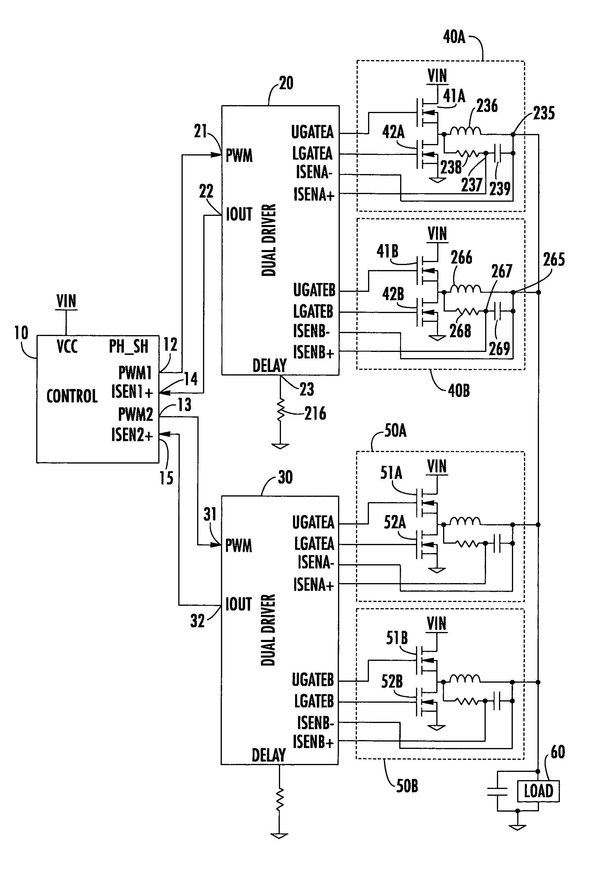
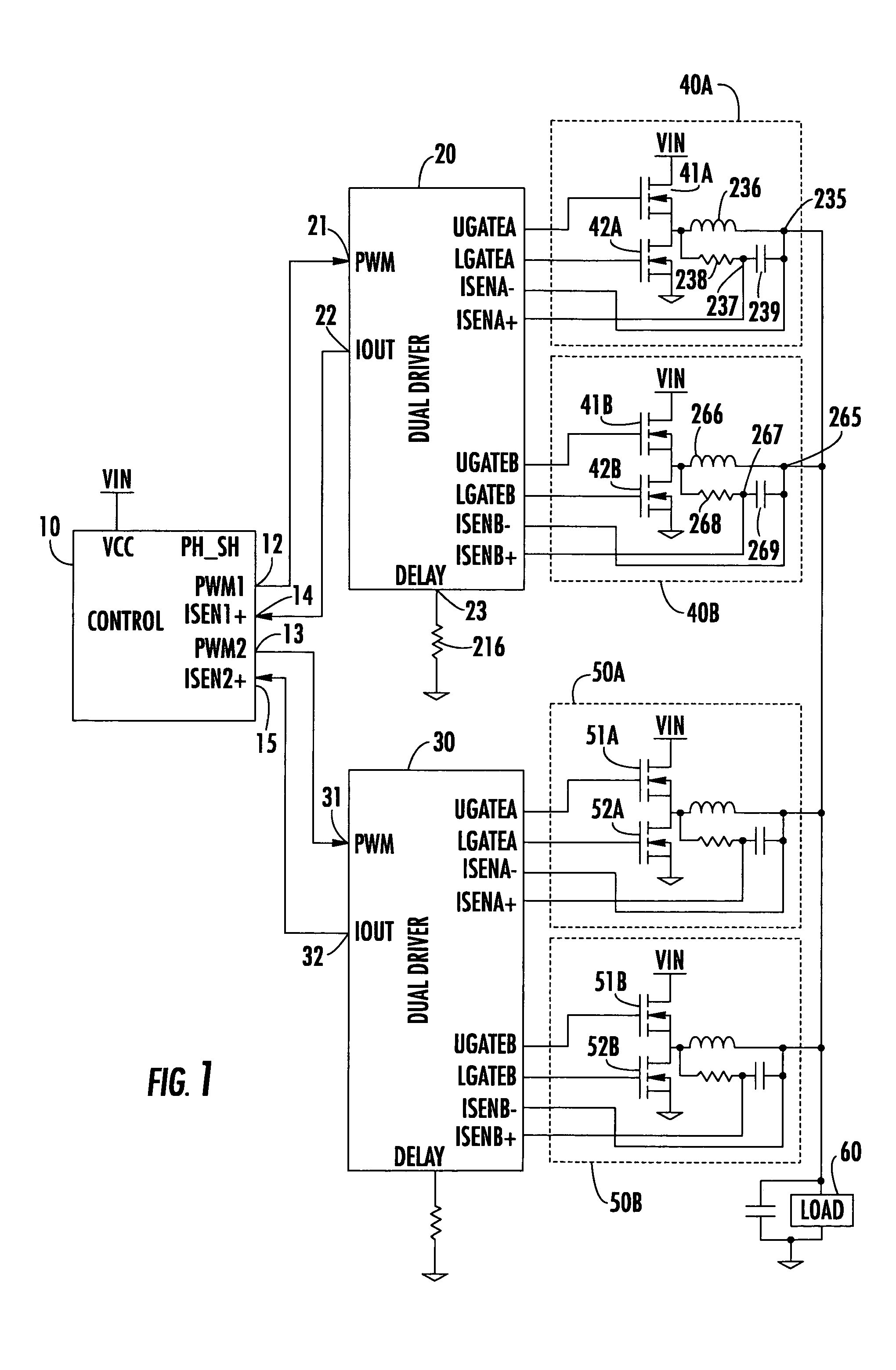
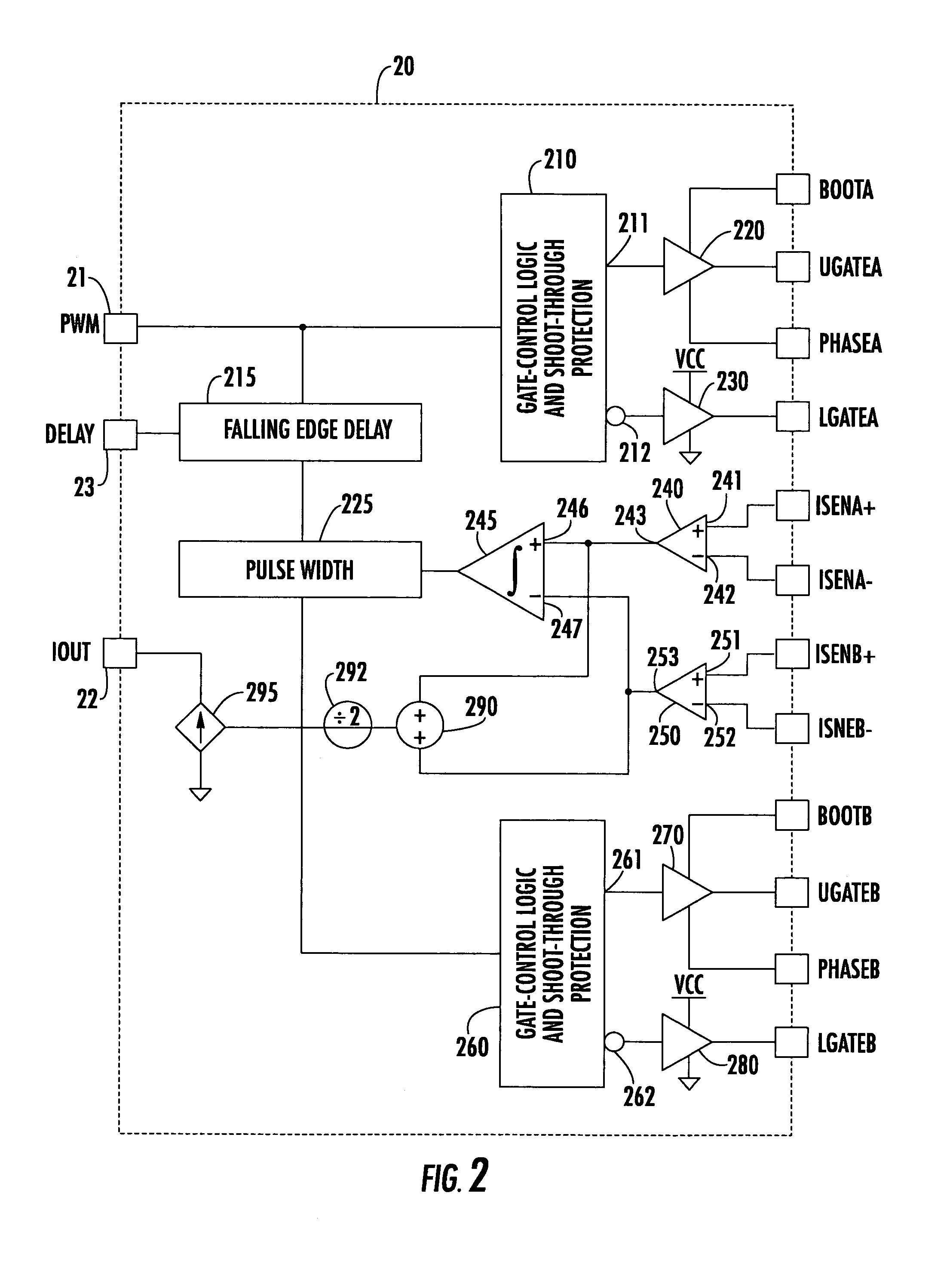
[0039]Attention is now further directed to FIG. 2, which shows the circuit architecture of each of the dual channel drivers 20 and 30. To reduce the complexity of the drawings, the following description will pertain to dual channel driver 20, it being understood that the description and illustration thereof applies equally to the dual channel driver 30 without any loss in generality. As shown in FIG. 2, the PWM input port 21, to which the PWM control signal is supplied from the supervisory controller 10, is coupled to a first A channel gate control logic section 210, which is of conventional configuration, and is used to apply gate or switching control signals to the ‘upper’ output channel switch 40A of the first pair of A and B channel switching circuits 40A and 40B.

[0040]For this purpose, gate control logic section 210 supplies a first output 211 through a first driver amplifier 220 to the UGATEA output for application to the gate of an upper MOSFET switch 41A of the A channel swi...

second embodiment

[0053]As described above, in the circuit architecture of a respective dual channel driver shown in FIG. 2, the output of the error amplifier 245 is used to adjust the width of the channel B PWM signal, as output by delay circuit 215, prior to its being applied to the channel B gate control logic section 260. The output of the channel B gate control logic section is then used to control the gate drive signals for a respective one of switching circuit channels 40B and 50B. In accordance with a respective dual channel driver diagrammatically illustrated in FIG. 6, the output of the error amplifier 245 is used to control gate turn-off propagation delay of high side gate drive (for trailing edge PWM signals) or turn-off-delay of low side gate drive (for leading edge PWM signals), so as to provide current balance between the A and B channels. In the embodiment of FIG. 6, the pulse width control circuit 225 of FIG. 2 is replaced by combinational logic 300, which is effective to implement t...


PUM


Abstract

A reduced pin count, dual channel driver interface is configured to interface a supervisory controller with a plurality of multi-phase output channel switching circuits of a multi-phase DC-DC regulator. Each dual channel driver is configured for placement relatively close to output channel sense points, so as to effectively reduce the distance that would otherwise have to be traversed by noise sensitive voltage signals. Sensed current representative signals are processed within the dual driver for current balance between a respective multi driver pair, and are combined to supply the controller with the average current signal of the dual channels. The controller uses this average current-information to adjust respective pulse width modulation signals that are supplied to the dual channel drivers.

Description

CROSS-REFERENCE TO RELATED APPLICATIONS[0001]The present application claims the benefit of previously filed, co-pending U.S. Application Ser. No. 60 / 514,758, filed Oct. 27, 2003, by Chun Cheung et al, entitled: “Method of Doubling the Phase Count in a Multi-Phase DC-DC Converter,” and co-pending U.S. Application Ser. No. 60 / 520,112, filed Nov. 14, 2003, by Chun Cheung, entitled: “Novel Current Balance Technique for Smart Dual Driver,” each application being assigned to the assignee of the present application and the disclosures of which are incorporated herein.FIELD OF THE INVENTION[0002]The present invention relates, in general, to multi-phase DC-DC regulator systems and subsystems therefor, and is particularly directed to the use of multi- (e.g., dual) channel driver circuits to interface a supervisory controller with a plurality of multi-phase output channel switching circuits. The multi-channel driver circuits, which contain current sensing circuitry, can be conveniently placed ...

Claims


Application Information

Patent Timeline
Patent Type & Authority Patents(United States)
IPC IPC(8): G05F1/613G05F1/40H02M3/158
CPCH02M3/1584
Inventor CHEUNG, CHUNHARRIS, MATTHEW B.
Owner INTERSIL INC
Why Eureka
Try Eureka