Surface discharge type plasma panel divided into a plurality of sub-screens

a plasma panel and sub-panel technology, applied in the direction of address electrodes, static indicating devices, instruments, etc., can solve the problems of inability to adjust the brightness of the display, the difficulty of grading the display by dividing the frame, and the single frame, so as to prevent an erroneous discharge and high speed addressing operation

Inactive Publication Date: 2006-04-11
MAXELL HLDG LTD
View PDF6 Cites 4 Cited by
  • Summary
  • Abstract
  • Description
  • Claims
  • Application Information

AI Technical Summary

Benefits of technology

[0017]It is a general object of the invention to prevent an erroneous discharge, i.e. an interference, across a border line of the divided screens in attempting a high speed addressing operation by dividing a screen.

Problems solved by technology

However, a single frame, that is a period for displaying a single picture, is unalterable.
Accordingly, the longer the addressing period becomes, the shorter the time length allocatable to the sustain period becomes, resulting in inadequate brightness of the display.
Moreover, the gradation display by dividing the frame become difficult.
However, in dividing all the sustain electrode pairs simply into two partial screens, there is a problem in that an erroneous discharge may take place across the border line where the second sustain electrode Y of the first sub-screen E11 faces the first sustain electrodes of the next line of the next partial screen E12.
However, in practically sealing the two glass substrates the symmetry may be somewhat deviated.

Method used


Image

  • Surface discharge type plasma panel divided into a plurality of sub-screens
  • Surface discharge type plasma panel divided into a plurality of sub-screens
  • Surface discharge type plasma panel divided into a plurality of sub-screens

Examples


Embodiment Construction

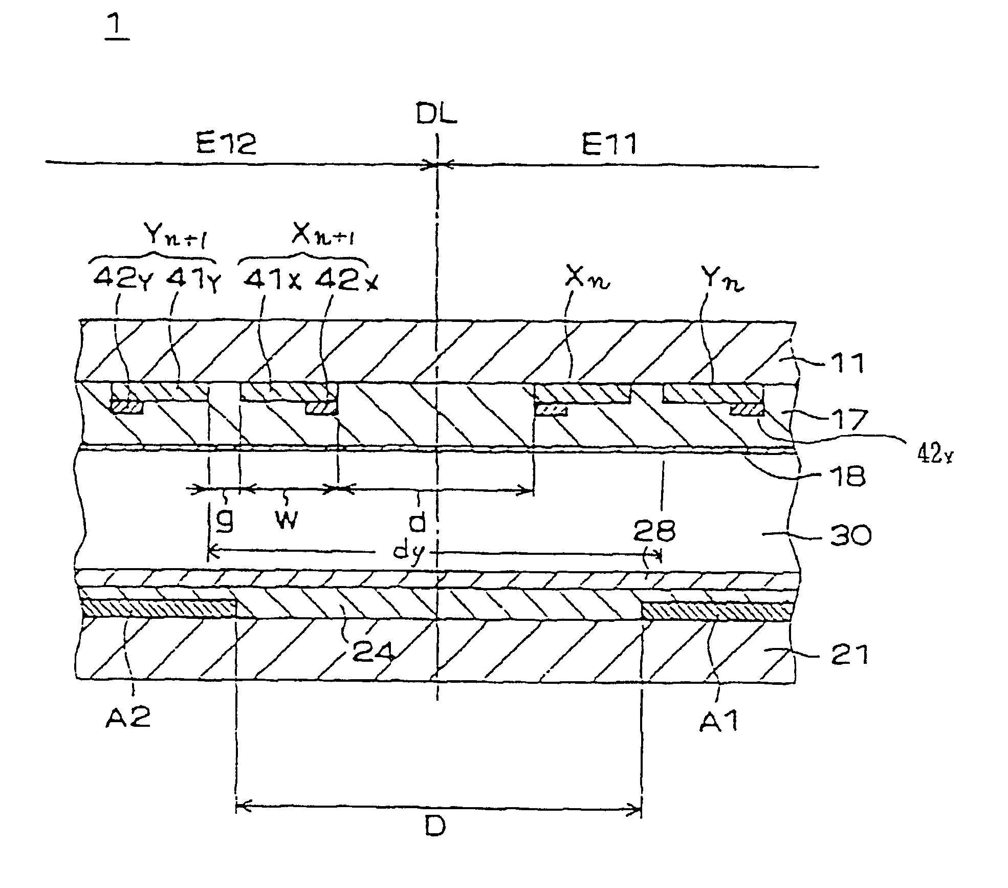
[0027]A preferred embodiment of the present invention is hereinafter described with reference to FIG. 4 schematically illustrating electrode configuration of a PDP, and FIG. 5 schematically illustrates a cross-sectional cut view of a PDP of the present invention.

[0028]PDP 4 is a surface discharge type PDP in which a single line is formed of a pair of first and second sustain electrodes X and Y, each in parallel and straight. The screen E1 is divided into two partial screens, that is first partial screen E11 and a second partial screen E12, in the row direction. The quantity of lines of the entire screen E1 is 2n, where the quantity of lines of each partial screen E11 and E12 is n. On each row of first partial screen E11 is provided with a first partial address electrode A1, and on each row of second partial screen E12 is provided with a second partial address electrode A1. A single pair of first and second address electrodes A1 and A2 aligned along a single row forms a single addres...


PUM


Abstract

A surface-discharge type PDP includes plural electrode pairs formed of first and second sustain electrodes arranged on a first substrate. Each pair extends along a line direction, and the first and second sustain electrodes are in parallel and adjacent to each other. Plural address electrodes arranged on a second substrate opposing the first substrate via a discharge space, each extending along a row direction, a matrix corresponding to a screen to be displayed is formed with the main electrodes and address electrodes, the address electrodes are orthogonal to the main electrodes, each of the address electrode is divided into, for example two partial address electrodes separated from each other by a border line located between adjacent main electrode pairs, whereby the screen is divided into two partial screens, wherein a first clearance between the partial address electrodes is substantially larger than a second clearance between main electrode pair adjacent across the border line. The arrangement order of the first and second sustain electrodes may preferably be such that first sustain electrodes of the first and second partial screens face each other via the border line, and the partial address electrodes may not cross over the first sustain electrodes nearest to the border line.

Description

[0001]This application is a divisional of application Ser. No. 09 / 951,749, filed Sep. 14, 2001, now U.S. Pat. No. Re. 38,819, which is reissue of U.S. Pat. No. 5,952,783 issued Sep. 12, 1999.BACKGROUND OF THE INVENTION[0002]1. Field of the Invention[0003]This invention relates to an AC type plasma display panel, referred to hereinafter as a PDP, of matrix formation, particularly to a PDP having a screen which is divided into a plurality of sub-screens.[0004]2. Description of the Related Arts[0005]A prior art surface discharge type PDP is hereinafter described with reference to FIG. 1 schematically illustrating a plan view of the electrode configuration, and FIG. 2 schematically illustrating a decomposition perspective view of the internal structure.[0006]Prior art PDP 80 includes a plurality of electrode pairs 12j of first and second sustain electrodes Xj & Yj in parallel with each other and extending straight, both of which may be called main electrodes, and a plurality of address ...

Claims


Application Information

Patent Timeline
Patent Type & Authority Patents(United States)
IPC IPC(8): G09G3/20G09G3/28H01J11/14H01J11/12H01J11/22H01J11/24H01J11/26H01J11/28H01J11/32H01J11/34H01J11/36H01J11/38H01J11/42H01J11/46H01J17/00H01J17/49
CPCG09G3/28G09G3/2932G09G3/298H01J11/12H01J11/26H01J11/32G09G3/2927H01J2211/323G09G2320/0209G09G2310/0221G09G3/294
Inventor KUROKI, SEIKINHAN, NGUYEN THANH
Owner MAXELL HLDG LTD
Why Eureka
Try Eureka