
Image reading apparatus and image reading method

a technology of image data and reading apparatus, which is applied in the direction of electrographic process, printing, instruments, etc., can solve the problems of determining the transport errors of documents, reducing the compactness and lightness of the apparatus, and reducing the noise of image data read from both surfaces

Active Publication Date: 2006-04-11
NISCA KK
View PDF11 Cites 40 Cited by
  • Summary
  • Abstract
  • Description
  • Claims
  • Application Information

AI Technical Summary

Benefits of technology

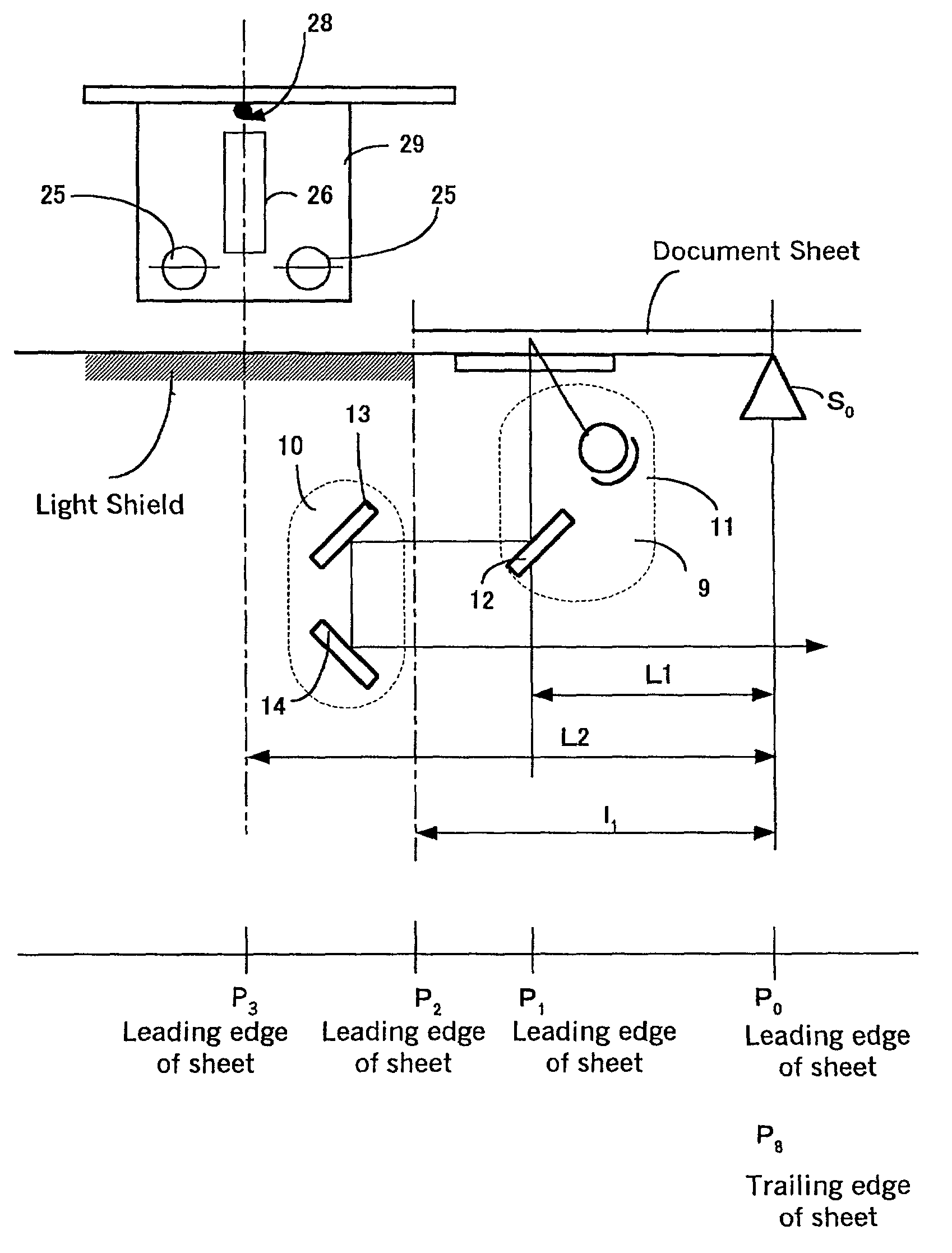
"The patent describes an image reading apparatus that can read indicia on both the upper and lower surfaces of a document or sheet. The apparatus includes a document detection sensor, first and second image sensors, and a controller device. The controller device starts reading from each sensor at the same time, but stops reading from each sensor at different times to minimize interference between the two sets of image data. The first and second image sensors are controlled to be lit just before and after the document is detected, and the quantity of light from each sensor is controlled to reduce noise and interference. The apparatus also includes a straight transport path to ensure accurate reading of the images on both surfaces. The invention allows for simultaneous reading of the image data from both surfaces, and a white plate is used to shield light from the first light source to prevent interference with the second image sensor. Overall, the apparatus improves image quality and efficiency in reading documents."

Problems solved by technology

Thus, by always monitoring the offset line count, transport errors of the document are determined.
If the upper surface reading position and the lower surface reading position are disclosed close to each other, there is increased a danger of the light from the light source device for illuminating one surface of the document passing through the document sheet and being detected by the image sensor on the other surface, so that the mutual interferences of the upper and lower light sources cause electronic noise in the image data read from both surfaces.
Therefore, if the reading position for the one or upper surface of the document and the reading position for the other or lower surface of the document are arranged in the same position, the apparatus will become more compact and lightweight, but image data read from both surfaces will cause noise to be generated.
In such case, if monitoring the line count offset according to the distance LD for the image signal of both surfaces, an unnecessary amount of image data is recorded, requiring the entire controller device to be more complex, thus making it impossible to lighten the weight of the apparatus and to make the overall apparatus more compact.

Method used


Image

  • Image reading apparatus and image reading method
  • Image reading apparatus and image reading method
  • Image reading apparatus and image reading method

Examples


Embodiment Construction

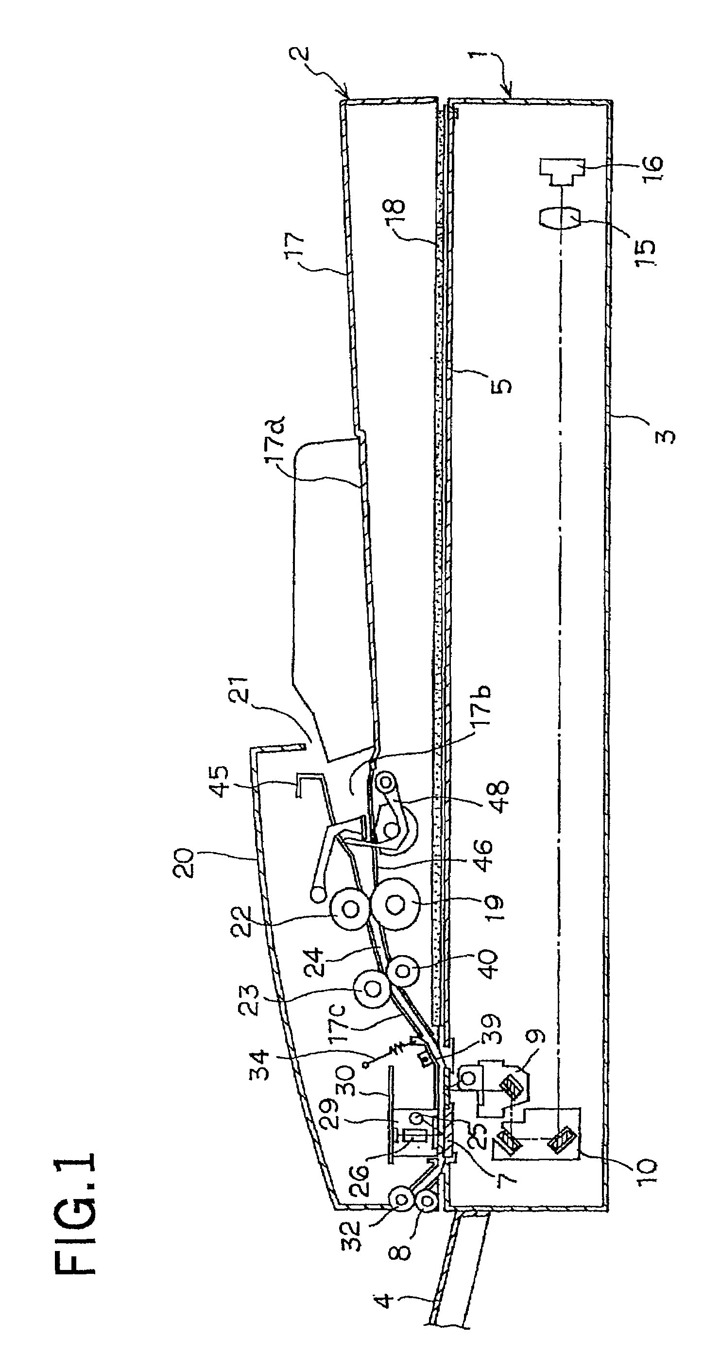
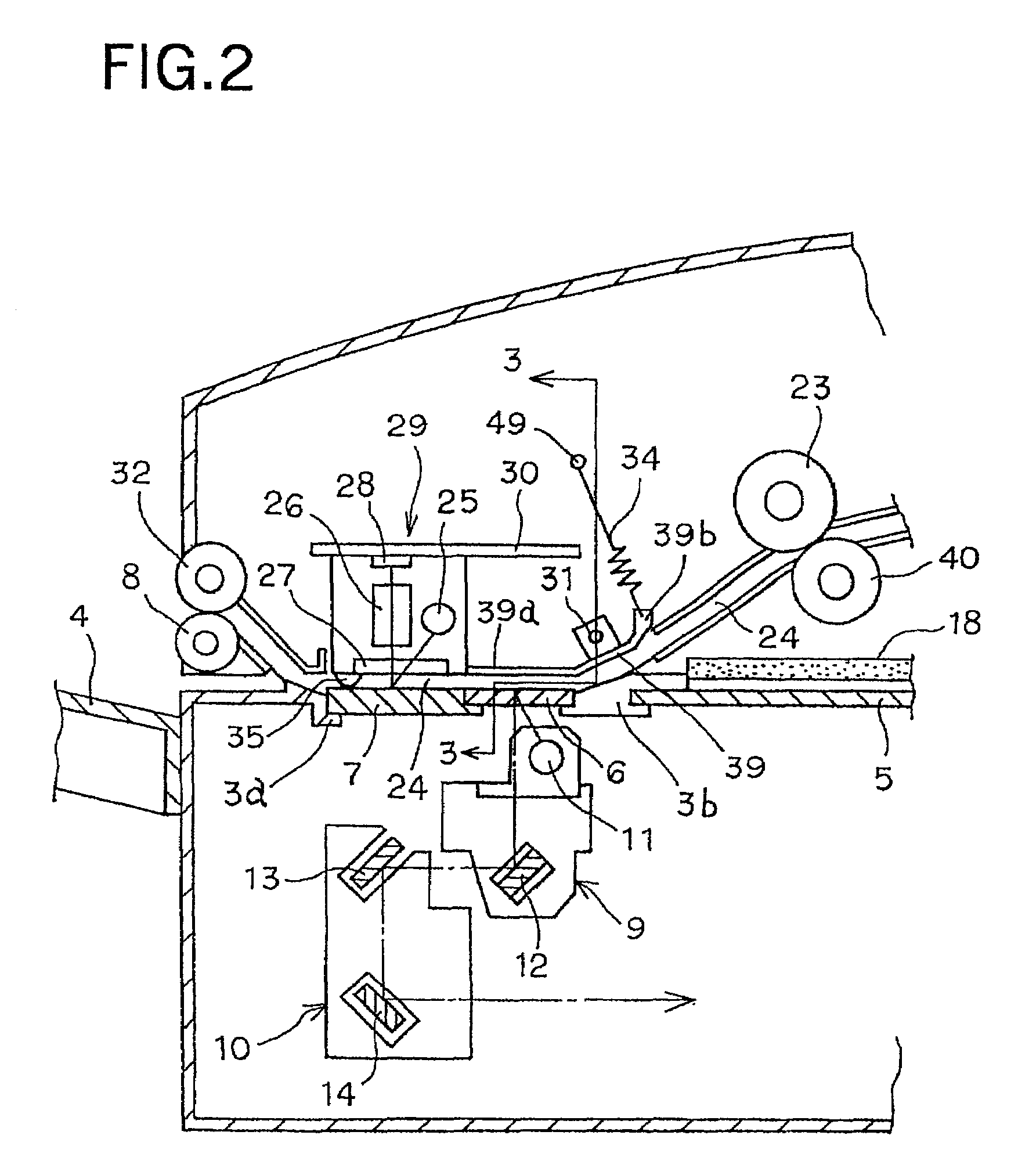
[0036]The following is a detailed explanation of the preferred embodiment of the present invention based on the figures provided. FIG. 1 is a longitudinal sectional view of the entire structure of the image reading apparatus relating to the invention. FIG. 2 is a partly enlarged sectional view of the essential members of FIG. 1. FIG. 3 is a sectional view taken along line 3—3 of FIG. 2. FIG. 4 is a perspective view from the upper part of FIG. 1 showing the upper unit of the image reading apparatus according to this embodiment with the top open upwardly.

[0037]In FIGS. 1 to 4, the upper unit 2 is mounted via hinges 33 to the main unit 1 to open upwardly. The outer side of the unit 1 is formed by a frame 3, and a discharge tray 4 is fastened to one side of the frame 3. Also, on the upper side of the frame on the opposite side of the discharge tray 4, there is incorporated a platen 5 (third platen) which is a transparent glass plate for placing a thick original for reading when the uppe...


PUM


Abstract

An image reading apparatus for reading indicia on the front and back surfaces of a document using two image sensors includes a document detection sensor to detect the document, a first image sensor for reading an image on one surface of the document, a second image sensor for reading an image on the other surface of the document, and a controller. The controller starts to read the image data from the first and second image sensors when prescribed amounts of time have passed after the document detection sensor detects the leading edge of the document, and stops the reading of the image data from the image sensors. The structure provides a lightweight and compact apparatus while reducing image noise caused by the mutual interferences of the light sources in reading the image data.

Description

BACKGROUND OF THE INVENTION AND RELATED ART STATEMENT[0001]This invention relates to an image reading apparatus and image reading method for scanning and optically reading a document image and outputting the electronic data. More particularly, this invention relates to an image reading apparatus equipped with two optical reading sensors for reading the images on the upper and lower surfaces of a document or sheet fed one by one from a document reception tray by an automatic document feeder commonly known as an ADF.[0002]Image reading apparatuses, normally called scanners, optically read the image of a document and convert the image into electronic data and transmit it to image forming apparatuses, such as personal computers, copy machines or facsimiles. Image forming apparatuses are also normally equipped with the following types of image reading apparatuses.[0003]The image reading apparatuses have image sensors for reading the images on a document or sheet transferred one by one fr...

Claims


Application Information

Patent Timeline
Patent Type & Authority Patents(United States)
IPC IPC(8): H04N1/04G03G15/00G03B27/50G06T1/00H04N1/00H04N1/203
CPCH04N1/203H04N1/00681
Inventor KANDA, TAKASHI
Owner NISCA KK
Learn More