Programmable controller with external terminals

a programmable controller and terminal technology, applied in the direction of electrical apparatus casings/cabinets/drawers, instruments, substation/switching arrangement casings, etc., can solve the problems of laborious and laborious hand-held completion of labeling fields, prone to error in label entry fields, etc., and achieve the effect of easy wiring of the programmable controller

Inactive Publication Date: 2006-04-11
SIEMENS AG
View PDF11 Cites 15 Cited by
  • Summary
  • Abstract
  • Description
  • Claims
  • Application Information

AI Technical Summary

Benefits of technology

[0008]The advantage of the invention is that, with a programmable controller of this type, inconsistencies between planning of a process signal, the representation in the labeling field and the actual wiring can be avoided. The consistency of the representation in the labeling field consequently ensured with the planning / programming also makes the wiring of the programmable controller easier.
[0009]It is generally customary that, when programming a programmable controller or when planning an automation project, signal names which make it easier for such project plans or programs of this type to be read, and consequently maintained, are allocated for the individual signals from or to the external technical process. A signal which is supplied by a limit switch positioned at one end of a track is correspondingly labeled, for example, as “limit switch track end”. A signal which is supplied by a filling level gage in a silo is correspondingly labeled, for example, as “silo full”. These signals pass via corresponding wiring into the programmable controller at the external terminals. It is consequently desirable to provide the signal and the line over which the signal is transmitted, or the external terminal on which the line is placed, with the same label.
[0010]In the past, this label was entered in corresponding labeling fields by hand. If the labeling field is an electrically activatable labeling field, the respective label for each labeling field can be prescribed in an electrical way and obtained for this purpose in particular on the basis of data which are already available in any case after the programming of the programmable controller or after the planning of the automation project.
[0011]If the external terminals are also led to the front side where the labeling field(s) are located, a clearly evident assignment of an external terminal to the respective labeling field is possible.
[0012]If each labeling field is an alphanumeric labeling field, signal labels can be represented in plain text in the same form as they are also shown in documentation.
[0013]If each labeling field is a dot-matrix field, there is an extended possibility for representation, so that, for example, special symbols can also be represented or that, for instance, each time a change in the status of the respective signal occurs the representation of the label is inverted. When a signal is present, the label could be displayed with bright script on a dark background and, when a signal is not present, the label could be displayed with dark script on a bright background. It goes without saying that colors can also be meaningfully used here if the labeling field has color capability. Altogether, this opens up the possibility of being able to dispense with light-emitting diodes, which today often display the signal status.

Problems solved by technology

The entering of a label in a labeling field is prone to error in a disadvantageous way, because it cannot be ensured that the labeling field assigned to an external terminal is correctly labeled.
Moreover, completing a labeling field by hand is labor-intensive.

Method used


Image

  • Programmable controller with external terminals
  • Programmable controller with external terminals

Examples


Embodiment Construction

[0018]Reference will now be made in detail to the preferred embodiments of the present invention, examples of which are illustrated in the accompanying drawings, wherein like reference numerals refer to like elements throughout.

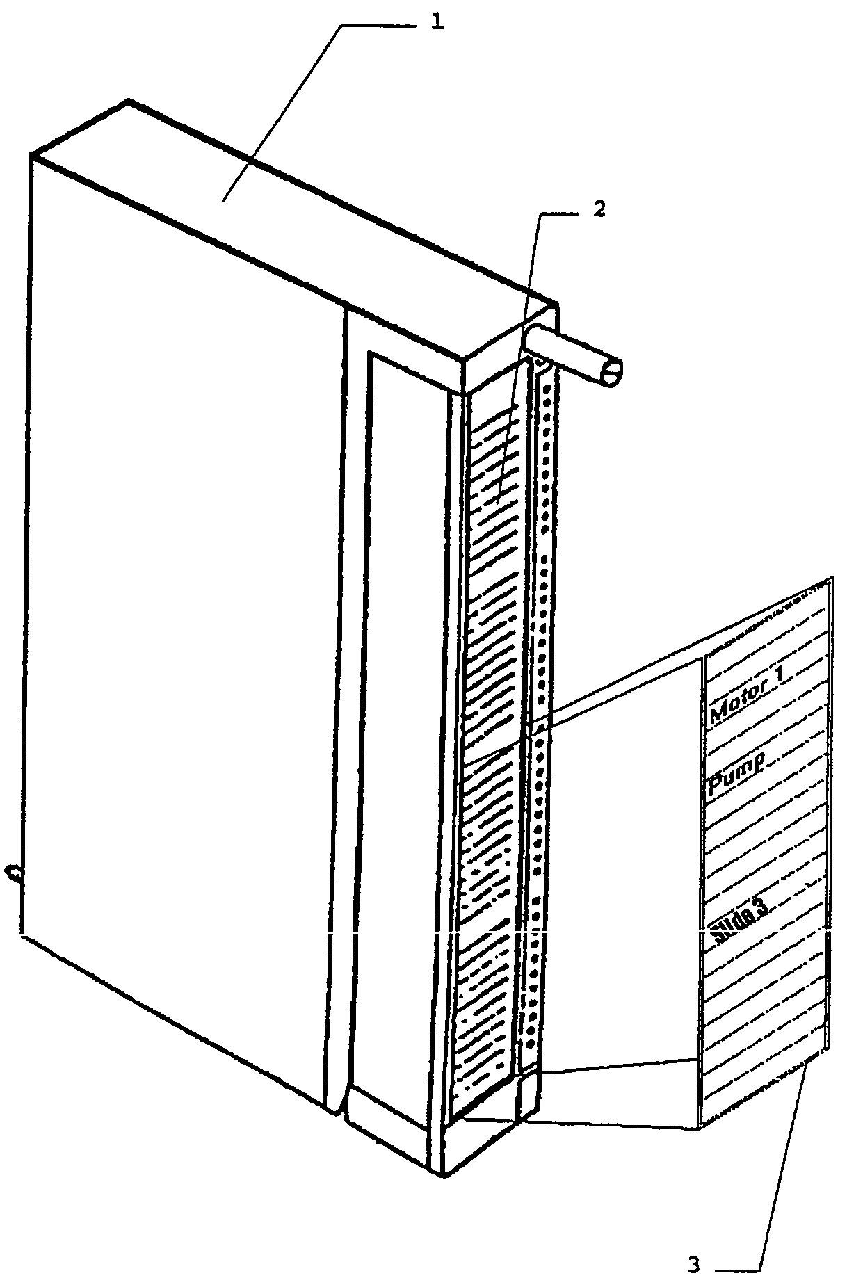
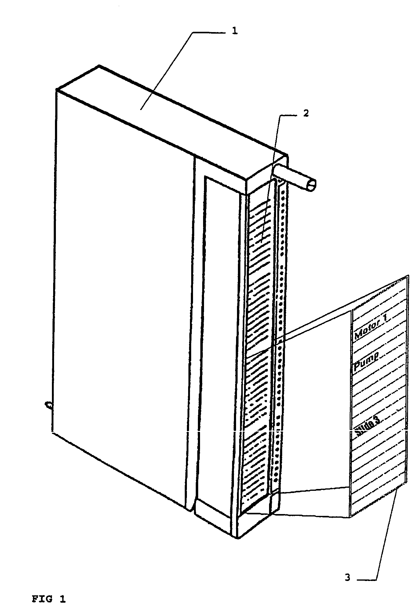
[0019]FIG. 1 shows a programmable controller 1, similar to what is described for example in EP 0 162 373. The known programmable controller has on a front side 2 with a labeling field. In such a labeling field, which for example comprises a paper strip, in the past entries have been made manually to label the various external terminals of the programmable controller 1.

[0020]According to the invention, it is envisaged to replace the previous labeling field with an electrically activatable labeling field 3. The electrically activatable labeling field 3 offers the possibility of respectively representing groups of alphanumeric characters in a number of rows, a row of the electrically activatable labeling field 3 being respectively assigned to an external termina...


PUM


Abstract

A programmable controller with external terminals is provided, in which an electrically activatable labeling field is provided for labeling the external terminals.

Description

CROSS REFERENCE TO RELATED APPLICATIONS[0001]This application is based on and hereby claims priority to German Application No. 10152348.3 filed on Oct. 24, 2001, the contents of which are hereby incorporated by reference.BACKGROUND OF THE INVENTION[0002]A programmable controller of the type to which the present invention is directed is known, for example, from DE 36 03 750 or from EP 0 162 373 or, for example, as a programmable controller with the designation Simatic S7-300 or Simatic S7-400 from Siemens AG.[0003]The term programmable controller refers both to a complete device and to individual modules, as they are known, or assemblies, which can be combined to form a complete device.[0004]The programmable controllers of DE 36 03 750 have on a front side, visible to a user or operator, a number of labeling fields. Each labeling field is assigned to an external terminal, so that the user or operator is informed by the label entered in the labeling field about the functionality of th...

Claims


Application Information

Patent Timeline
Patent Type & Authority Patents(United States)
IPC IPC(8): G06F1/16H05K7/14
CPCH05K7/1481H05K5/0252
Inventor BOCK, GUNTHER
Owner SIEMENS AG
Why Eureka
Try Eureka