Repeater for customer premises

a customer-owned, repeater technology, applied in the field of repeaters for customer premises, can solve problems such as foil backing interference with the reception and transmission of radio signals from inside the residence, attendant problems, and failure to meet customer requirements,

a customer-owned, repeater technology, applied in the field of repeaters for customer premises, can solve problems such as foil backing interference with the reception and transmission of radio signals from inside the residence, attendant problems, and failure to meet customer requirements,

US7027770B2Active Publication Date: 2006-04-11COMMSCOPE TECH LLC

Image

  • Repeater for customer premises
  • Repeater for customer premises
  • Repeater for customer premises

Examples


Embodiment Construction

[0013]While several embodiments of the invention have been shown and will be described hereinafter, it will be understood that the invention is not limited to the specific embodiments described. For example, while the illustrated embodiments show particular combinations of elements, those skilled in the art may recognize one or more different subcombinations or manners in which various elements from the various embodiments may be combined to form yet other embodiments, subcombinations or variations.

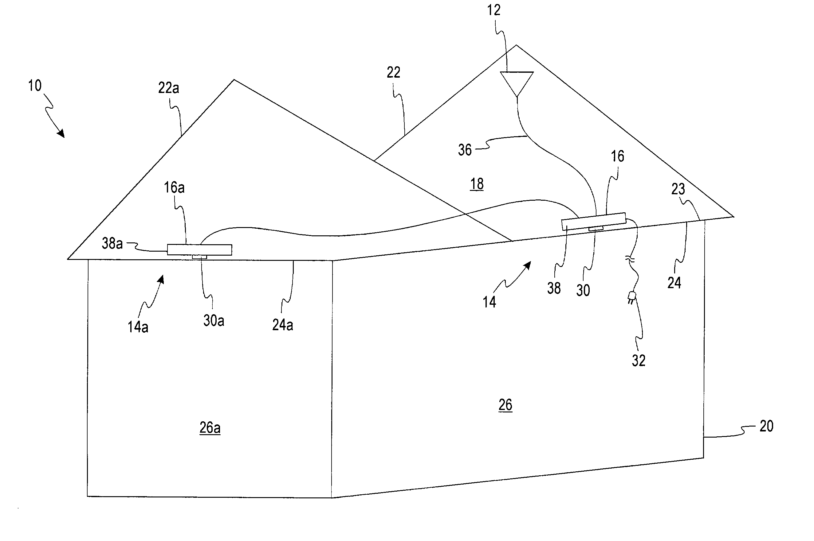
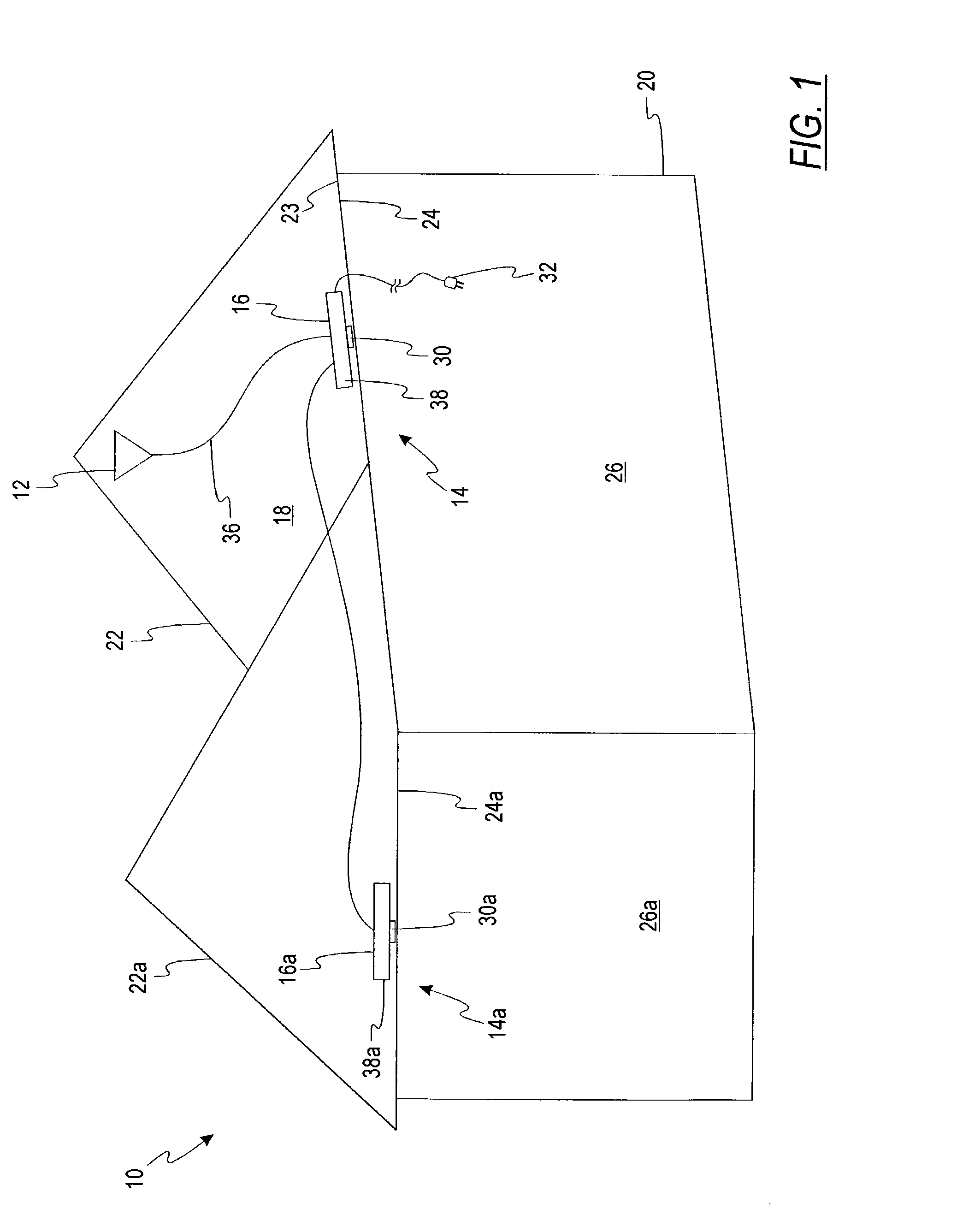
[0014]The herein-described embodiments utilize a repeater for use in connection with enhancing reception of wireless communications in an architectural structure using a housing that incorporates both a null antenna capable of being oriented to provide an antenna beam directed into an interior portion of the architectural structure, and a repeater circuit that is configured to provide bi-directional exchange of radio frequency signals between the null antenna and a donor antenna. As will ...


PUM


Abstract

A repeater for use in connection with enhancing reception of wireless communications in an architectural structure utilizes a housing that incorporates both a null antenna capable of being oriented to provide an antenna beam directed into an interior portion of the architectural structure, and a repeater circuit that is configured to provide bi-directional exchange of radio frequency signals between the null antenna and a donor antenna. The donor antenna may also be mounted to the housing, or alternatively may be coupled to the housing via a cable or other communications path. The repeater is suitable for installation in an attic, or alternatively, within a room or other inhabitable area of a structure.

Description

RELATED APPLICATIONS[0001]This application claims the filing benefit and priority of U.S. Provisional Application entitled ā€œRepeater for Customer Premises,ā€ Ser. No. 60 / 292,762, filed May 22, 2001, and incorporates that application by reference herein in its entirety.FIELD OF THE INVENTION[0002]This invention is directed generally to wireless communications and more particularly to a consumer unit for facilitating receipt and transmission of wireless communications at the customer premises.BACKGROUND OF THE INVENTION[0003]Various mobile communication services such as cellular telephones, using PCS or other radio frequency (RF) protocols are becoming increasingly widespread. Many consumers have gone so far as considering eliminating so-called land-line telephone service in favor of wireless services. Accordingly, for many such cellular customers, it has become increasingly desirable to obtain clear signals within the home or residence.[0004]However, the provision of reliable wireless...

Claims


Application Information

Patent Timeline
11 Apr 2006
Publication
US7027770B2
IPC
H04B7/15; H01Q1/00; H01Q1/12
CPC
H01Q1/007; H01Q1/1285; H01Q1/1271
Inventors
JUDD, MANO D.; ALFORD, JAMES L.