Nested channel ducts for nozzle construction and the like

Inactive Publication Date: 2006-04-18
PRATT & WHITNEY CANADA CORP
View PDF37 Cites 51 Cited by
  • Summary
  • Abstract
  • Description
  • Claims
  • Application Information

AI Technical Summary

Benefits of technology

[0005]It is an object of the present invention to provide an improved f

Problems solved by technology

Prior art multiple channel systems are cumbersome,

Method used


Image

  • Nested channel ducts for nozzle construction and the like
  • Nested channel ducts for nozzle construction and the like
  • Nested channel ducts for nozzle construction and the like

Examples


Embodiment Construction

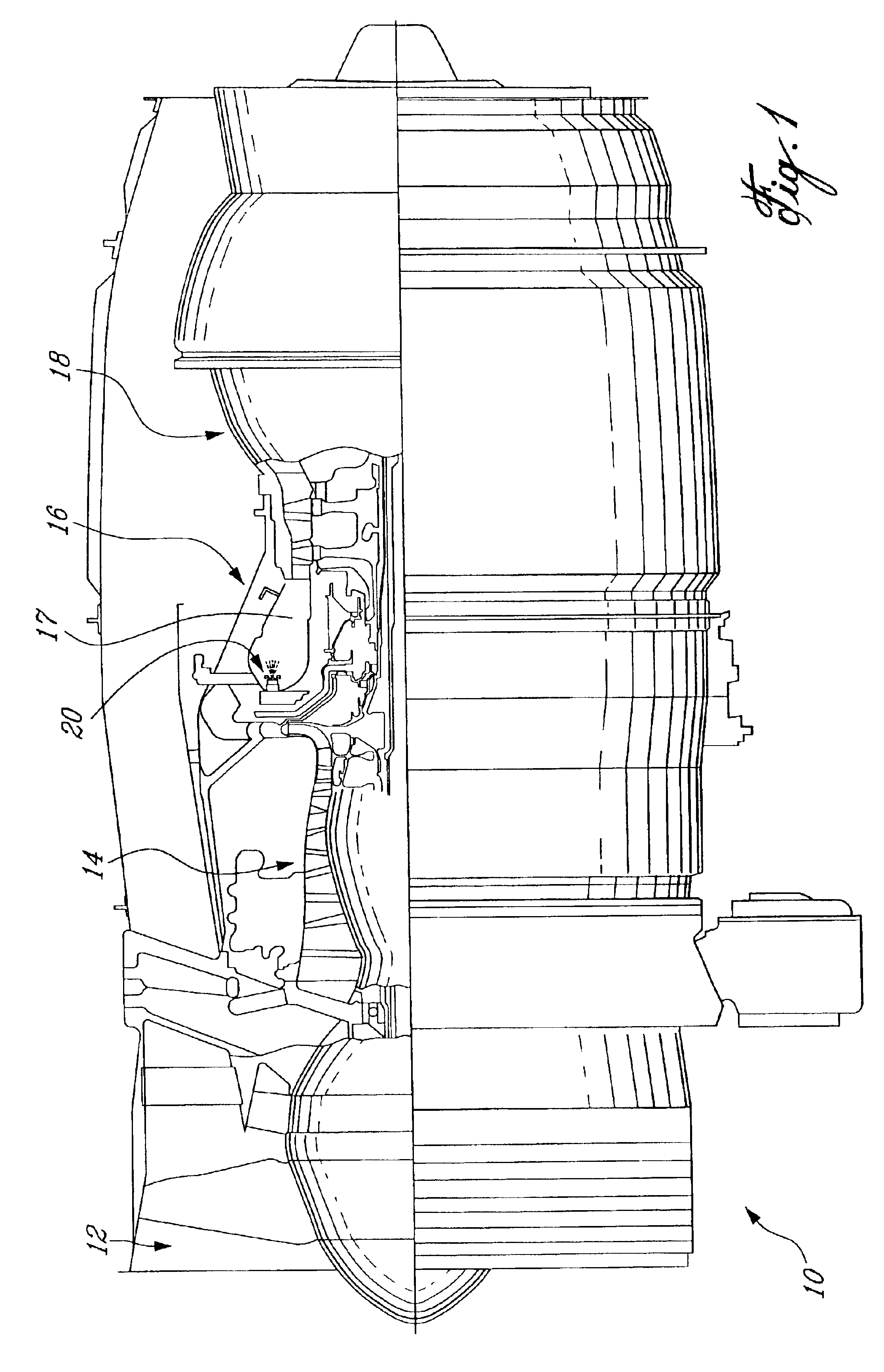
[0016]FIG. 1 illustrates a gas turbine engine 10 generally comprising, in serial flow communication, a fan 12 through which ambient air is propelled, a multistage compressor section 14 for pressurizing the air, a combustion section 16 in which the compressed air is mixed with fuel atomized into a combustion chamber 17 by a fuel injection system comprising a fuel injection nozzle assembly 20, the mixture being subsequently ignited for generating hot combustion gases before passing through a turbine section 18 for extracting energy from the combustion gases.

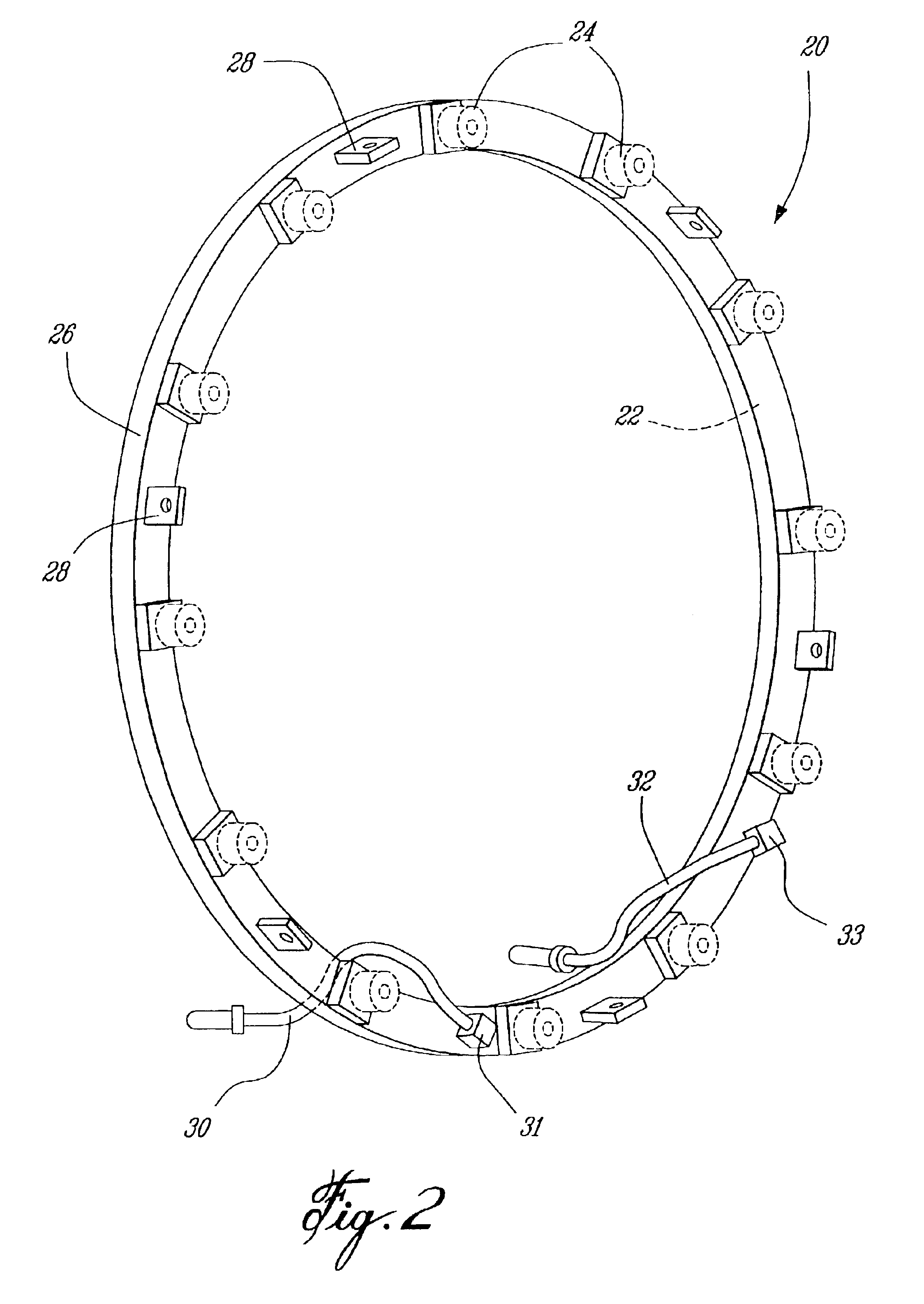
[0017]Referring to FIG. 2, the fuel injection nozzle assembly 20 comprises an annular fuel manifold ring 22 generally disposed within the combustion chamber 17 of the engine, and mounted via several integral attachment lugs 28 for fixing the annular ring 22 to an appropriate support structure. The annular fuel manifold ring 22 comprises a plurality of fuel injector spray tip assemblies 24 thereon, which atomize the fuel for combust...


PUM


Abstract

A multiple conduit system for a gas turbine engine, the multiple conduit system extending between a plurality of conduit inlet and outlets. A channel is formed in a surface of a gas turbine engine component, and the channel is adapted for conveying a fluid flow from an inlet to an outlet. At least a first sealing member is disposed within the channel and divides the channel into at least a first discrete conduit and a second discrete conduit. A second sealing member encloses the channel to define the second discrete conduit. The first and second discrete conduits are each adapted to direct an independent fluid flow from respective inlets to respective outlets.

Description

TECHNICAL FIELD[0001]The present invention relates generally to gas turbine engines, and more particularly to a nested channel configuration for use in fuel manifolds, nozzle stems and the like.BACKGROUND OF THE INVENTION[0002]Fuel nozzles which supply fuel to a combustion chamber in a gas turbine engine are well known in the art. Generally, a plurality of circumferentially distributed fuel nozzles forming a nozzle array in the combustion chamber are used to ensure sufficient distribution of the fuel. The fuel nozzle array typically comprises a plurality of injector tip assemblies for atomizing fuel into the combustion chamber, the injector tips being connected to an outer fuel manifold via nozzle stems.[0003]Some conventional nozzle systems define duel adjacent fuel passages, sometimes concentrically disposed within an outer tube. In an effort to provide a dual passage stem member which is relatively simpler and more economical to manufacture, it is also known to use a stem compris...

Claims


Application Information

Patent Timeline
IPC IPC(8): F02C7/22F23R3/00F23K5/06F02C7/232F23R3/28
CPCF02C7/222F23R3/283F23K5/06
Inventor PROCIW, LEV ALEXANDERSHAFIQUE, HARRISSOKALSKI, JOHNPELLETIER, CLAUDE RAYMOND
Owner PRATT & WHITNEY CANADA CORP
Why Eureka
Try Eureka