Vibration type angular velocity sensor

a technology of angular velocity sensor and vibration type, which is applied in the direction of acceleration measurement using interia force, turn-sensitive devices, instruments, etc., can solve the problems of deteriorating the sensing accuracy of the sensor, affecting the detection accuracy of differential waveform detection, and individual differences in angular velocity sensing properties of the sensor, so as to improve the detection accuracy based on the differential waveform detection, the effect of suppressing the aging change of once adjusted valu

Inactive Publication Date: 2006-04-18
DENSO CORP
View PDF10 Cites 7 Cited by
  • Summary
  • Abstract
  • Description
  • Claims
  • Application Information

AI Technical Summary

Benefits of technology

[0016]Furthermore, the analog input gain adjustment may be done only once, for example, before shipping the sensor. In this case, it is preferable that the variable resistor used for the analog input gain adjustment has a resistance value being irreversibly variable and adjustable only in a predetermined direction, so as to suppress the aging change of once adjusted value. More specifically, the variable resistor is preferably a laser trimmable resistor. When processed by the laser beam, the configuration of this laser trimmable resistor changes physically and irreversibly. The once-processed configuration of the laser trimmable resistor is stable and remains unchanged until the laser trimming processing is applied again. This is advantageous in that the resistance value and the adjusted analog input gain value can remain constant.
[0017]Furthermore, two vibration type sensor units may cause the difference not only in the in-phase component to be detected but also in the phase of the angular velocity sensing waveform. For example, in the case that the mechanical resonance characteristics of these vibrators in the angular velocity sensing direction (more specifically, the resonance characteristic frequencies) are different from each other in both sensor units, it is known from the elastic vibration theory that the vibration waveform phase changes according to the difference between an actual frequency of the vibrator and its characteristic frequency. Such differences appearing in the resonance characteristics are usually brought by the difference in the elastic coefficient between two elastic support members that allow the vibrator to oscillate relative to a fixed fulcrum. If any phase difference is produced between two angular velocity sensing waveforms, a significant differential component derived from such a phase difference will reside even after the above-described gain adjustment is carried out to adjust the in-phase component levels. Thus, the angular velocity sensing accuracy deteriorates. It is hence desirable to provide phase adjusting means for adjusting an input waveform phase at least one of the first angular velocity sensing waveform and the second angular velocity waveform to be entered into the differential waveform detecting means. The phase adjustment carried out by the phase adjusting means can reduce the phase difference before the differential waveform is generated, even if such a phase difference is produced between both waveforms. Thus, the angular velocity sensing accuracy in the detection based on the differential waveform can be improved.
[0018]Moreover, according to the vibration type angular velocity sensor of the present invention, it is possible to provide a signal processing section for each output of the first and second sensor units to remove a noise component having a frequency different from a driving frequency of the vibrator. The signal processing section can effectively remove the previously described unnecessary acceleration components residing in a frequency region far from the driving frequency. However, when the in-phase components acting to respective vibrators of the first and second sensor units include a proximity noise oscillatory component within a frequency region ranging to ±50% about the driving frequency (i.e. a frequency region having its center positioned on the driving frequency and a width of ±50% with respect to this center), the above signal processing section may not work sufficiently. Hence, it is preferable that the input gain adjusting means executes an amplitude adjustment for a sensor output waveform produced as a composite output of the angular velocity oscillatory component and the proximity noise oscillatory component, for at least one of the first and second sensor units. As a result, it becomes possible to reduce a relative amplitude difference between two proximity noise oscillatory components of respective sensor units. Especially, when the proximity noise oscillatory component is within a frequency region ranging to ±10% about the driving frequency (i.e. a frequency region having its center positioned on the driving frequency and a width of ±10% with respect to this center), it is almost impossible to remove this proximity noise oscillatory component even if the signal processing section enhances the filtering accuracy. Hence, the above arrangement brings remarkable effects.

Problems solved by technology

These unnecessary acceleration components appear as noises against the angular velocity to be sensed and accordingly deteriorate the sensing accuracy of the sensor when this sensor is used in detecting the traveling direction of the automotive vehicle.
These components are inevitably subjected to manufacturing errors that possibly cause sensor individual differences in their angular velocity sensing properties.
The angular velocity sensing accuracy will thus deteriorate.
However, this system is not effective at all in reducing adverse influences given by the variation factors other than the bias voltage, such as the weight and size of the vibrator (e.g. detection weight), the specifications of the vibrator driving section, or the electrode area of the vibration detecting capacitor.

Method used


Image

  • Vibration type angular velocity sensor
  • Vibration type angular velocity sensor
  • Vibration type angular velocity sensor

Examples


Embodiment Construction

[0034]Preferred embodiment of the present invention will be explained hereinafter with reference to attached drawings.

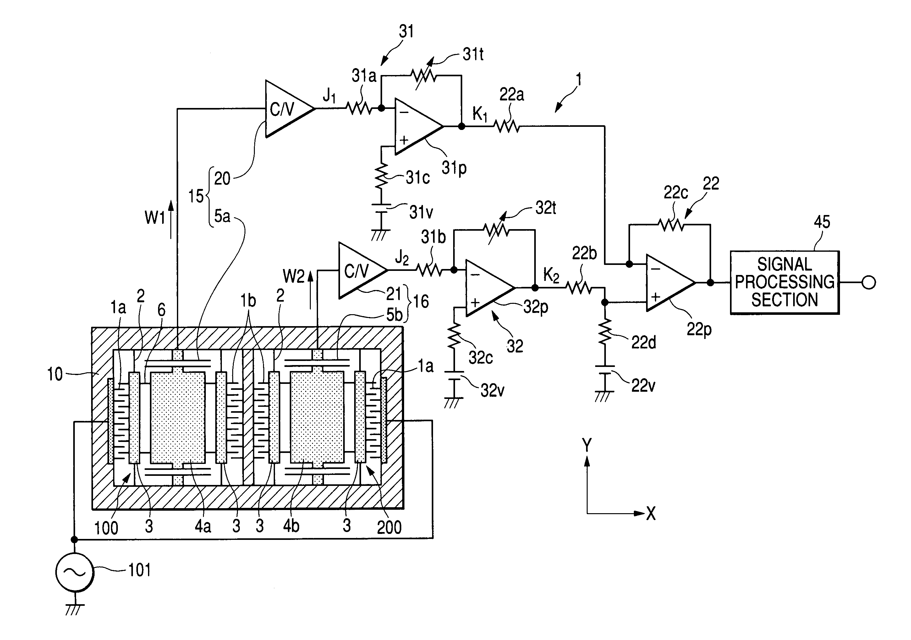
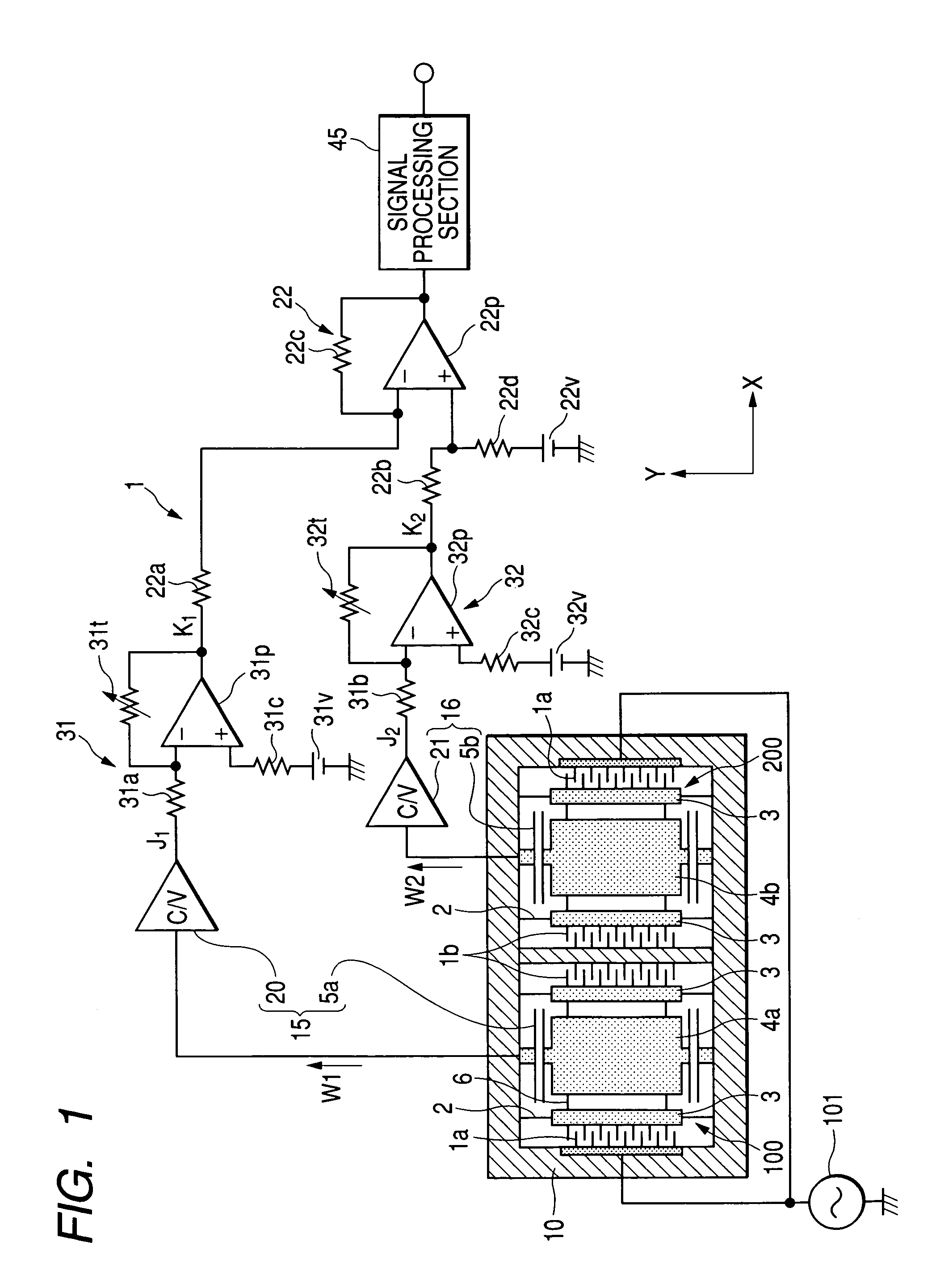
[0035]FIG. 1 is a circuit diagram showing an overall arrangement of a vibration type angular velocity sensor (that may be simply referred to as an “angular velocity sensor,” hereinafter) in accordance with a preferred embodiment of the present invention. The vibration type angular velocity sensor 1 has a sensing section that consists of a first sensor unit 100 and a second sensor unit 200. The first sensor unit 100 includes a vibrator (e.g. weight) 4a and a sensing waveform generating section 15, while the second sensor unit 200 includes a vibrator (e.g. weight) 4b and a sensing waveform generating sections 16. The vibrators 4a and 4b oscillate in a predetermined standard vibrating direction X. When an angular velocity is applied to respective vibrators 4a and 4b, an angular velocity oscillatory component is generated in a predetermined angular velocity sensing direc...


PUM


Abstract

To cancel in-phase components acting on vibrators of first and second sensor units in an angular velocity sensing direction Y, a differential amplification circuit obtains a differential waveform between a first angular velocity sensing waveform J1 and a second angular velocity waveform J2. Furthermore, to reduce a residual in-phase component of the obtained differential waveform, input gain adjusting circuits adjust an input gain of the first angular velocity sensing waveform J1 and an input gain of the second angular velocity sensing waveform J2 before these waveforms J1 and J2 are entered into the differential amplification circuit.

Description

BACKGROUND OF THE INVENTION[0001]This invention relates to a vibration type or oscillatory angular velocity sensor.[0002]The angular velocity sensors (gyro sensors) are chiefly classified into a mechanical type utilizing the precession of a rotary body, an optical type utilizing a light-receiving timing change in accordance with the revolution of a laser beam rotating in a casing, a fluid type sensing a hot wire temperature representing an injection amount of a sensing gas changing in accordance with the rotation of a casing when the sensing gas is injected to a hot wire in the casing, and others.[0003]On the other hand, the angular velocity sensors are recently required for detecting the traveling direction of an automotive vehicle in a car navigation system or the like. The vibration type angular velocity sensor is preferably employed in such systems because the vibration type is advantageous in cost and weight compared with the above-described other types. The vibration type angu...

Claims


Application Information

Patent Timeline
Patent Type & Authority Patents(United States)
IPC IPC(8): G01P9/04G01P3/44G01C19/56G01C19/5719G01C19/5726G01C19/5747
CPCG01C19/5719A01D46/26A01D2046/262
Inventor HIGUCHI, HIROFUMIITO, TAKESHI
Owner DENSO CORP
Why Eureka
Try Eureka