Bar gun

a bar gun and handle technology, applied in the direction of liquid dispensing, liquid transferring device, packaging, etc., can solve the problems of one-hand operation being more difficult, current bar guns causing handling problems, and poor visibility of buttons and beverage associated with those buttons

Inactive Publication Date: 2006-04-18
MCCANNS ENG & MFG CO
View PDF15 Cites 25 Cited by
  • Summary
  • Abstract
  • Description
  • Claims
  • Application Information

AI Technical Summary

Benefits of technology

[0007]The present invention is directed to an improved bar gun having a housing assembly with valve seats, separate inlets to those seats and separate outlets from those sea

Problems solved by technology

The size of the current bar guns create handling problems.
Such adjustments make one-hand operation more difficult.
Another common problem associated with conventional mechanical bar guns is the poor visibility of the buttons and the identification of the beverage associated with those buttons.
However, bar guns are typically used in poorly lit environments, such as in bars or nightclubs, where decals have limited effec

Method used


Image

  • Bar gun
  • Bar gun
  • Bar gun

Examples


Embodiment Construction

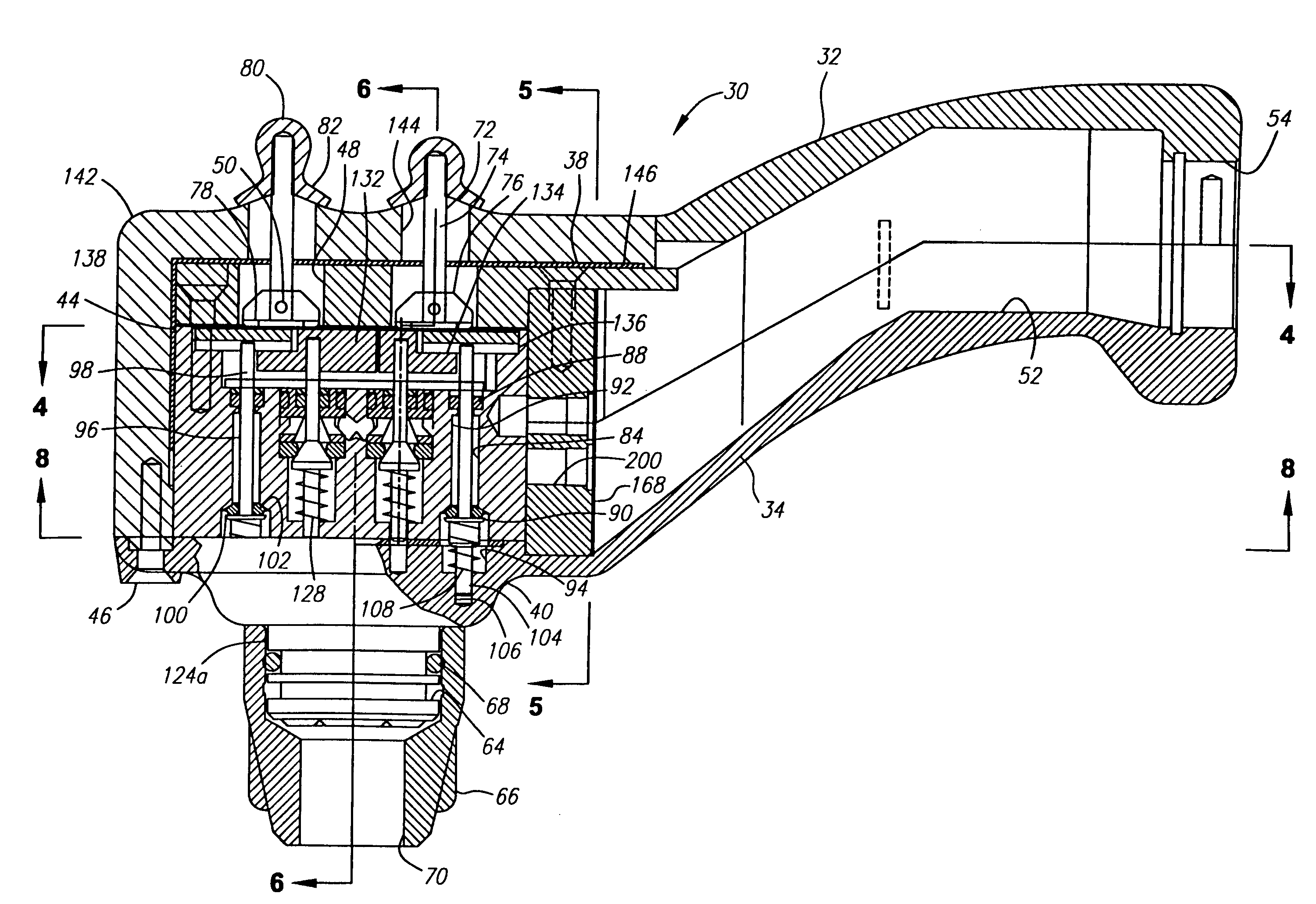
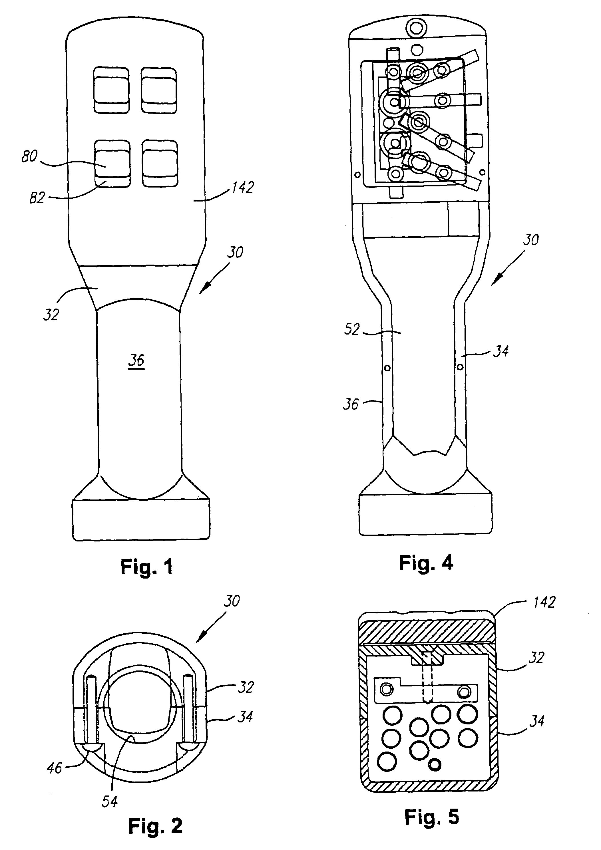
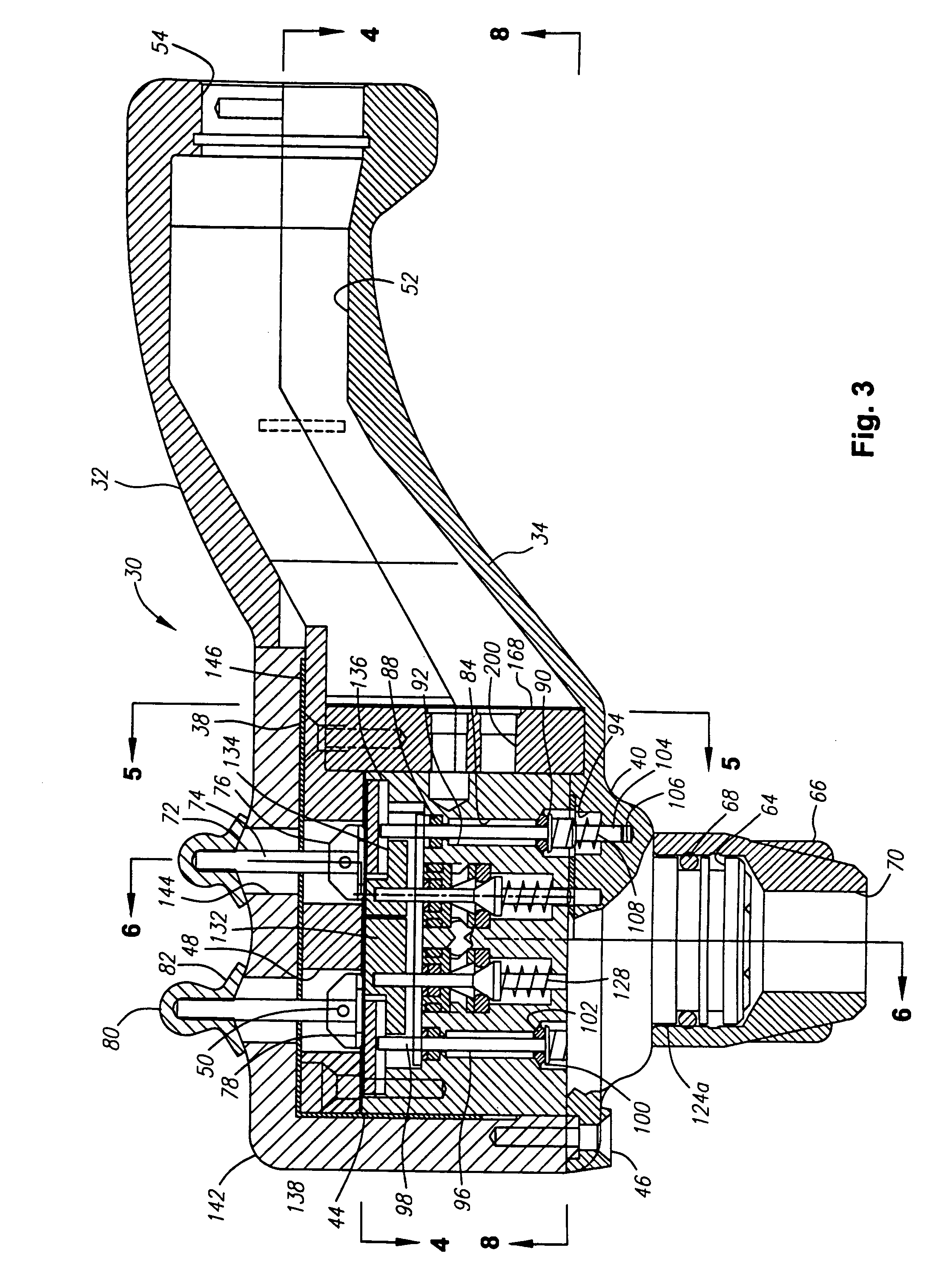
[0035]Turning in detail to the drawings, a bar gun embodiment is shown to include four actuators. Any reasonable number of actuators may be employed and the layout of a second embodiment having six actuators is illustrated in the patterns of FIGS. 13 through 15. But for the number of actuators, associated valves and valve components and the accommodation thereof, there are no differences between embodiments having different numbers of actuators.

[0036]A housing assembly, generally designated 30, is conveniently fabricated of an upper piece 32 and a lower piece 34. The upper piece 32 includes an upper portion of an elongate handle 36 and a mounting plate 38. The lower piece 34 includes a lower portion of the elongate mounting handle 36 and a spout support 40 with a spout manifold 42 depending therefrom. A valve block 44, positioned between the mounting plate 38 and the spout support 40 also is part of the housing assembly 30. These three principal components, the mounting plate 38, th...


PUM


Abstract

A bar gun includes a housing assembly with valve seats, separate inlets to those seats and separate outlets from those seats. Valve elements are operatively mounted to the housing to cooperate with the valve seats. Actuators are pivotally mounted relative to the housing assembly to provide two valve actuations per actuator. A bar gun handle is arranged relative to the actuators to improve access to the actuator levers. A low-current electro-luminescent element is arranged behind a light-transmitting cover to improve visibility of labeling on the gun. Actuator bars are pivotally mounted below valve lifters on the actuators. Syrup valve elements and carbonated and noncarbonated water elements are located below the actuator bars to be actuated by the actuator bars to create the appropriate mix. Lost motion is provided between the actuator bars and the syrup valve elements to accommodate differentials in pressures between the waters and the syrups. The connector to the bar gun includes equal length supply tubes contained within a sheath. The tube end pieces at either end include grouped hole patterns. Shut off valves are employed at the tube end piece at the supply end of the connector which close the supply passages when the end piece is removed. Manual valves are also available to shut off individual supply lines.

Description

BACKGROUND OF THE INVENTION[0001]The field of the present invention is apparatus for dispensing beverages and, in particular, handheld bar guns for dispensing a number of different beverages from the same device.[0002]Bar guns that provide an operator with the ability to dispense a number of different beverages by selecting among buttons are common in the bar service industry. Typical mechanical handheld bar guns have valves that dispense pressurized liquid through a discharge spout when an appropriate button is depressed. Each valve normally has a valve seat including an O-ring, a valve element and a retainer spring that holds the valve element biased against the seat. The button is depressed with sufficient force to overcome the spring force closing the valve to dispense liquid. Once the valve is open, the pressurized liquid flows through the valve and out of the discharge spout into, for example, a glass for serving. Typically the bar gun is supplied with syrup, carbonated water ...

Claims


Application Information

Patent Timeline
IPC IPC(8): B67D5/06B67D7/06B67D1/00
CPCB67D1/0084B67D1/0872B67D1/0086B67D2210/00086
Inventor MCCANN, GERALD P.ZATULOVSKY, LEONIDVERLEY, DONALD J.
Owner MCCANNS ENG & MFG CO
Why Eureka
Try Eureka