Load bearing window

a technology of load bearing and window, which is applied in the field of aircraft windows, can solve the problems of limited strength capability of polymer windows, limited capabilities of current transparent window materials, and windows that require a heavy support structure, and achieve the effect of small cross sectional area

Active Publication Date: 2006-04-18
THE BOEING CO
View PDF23 Cites 64 Cited by
  • Summary
  • Abstract
  • Description
  • Claims
  • Application Information

AI Technical Summary

Benefits of technology

[0006]The features, functions, and advantages can be achieved independently in various embodiments of the present inventions or may be combined in yet other embodiments.

Problems solved by technology

This is due, in part, to the limited capabilities of current transparent window materials and also due to the heavy and complex support structure needed to support these windows within the frame of the aircraft.
While very successful in the industry and exhibiting such useful qualities as high durability and easy formation of complex shapes, these polymer windows do have a limited strength capability.
Moreover, these windows require a heavy support structure in order to support the window within the structural skin of the aircraft.
However, each component added, in turn, increases the cost and weight of the completed window assembly, thereby providing an incentive to keep passenger windows relatively small.

Method used


Image

  • Load bearing window
  • Load bearing window
  • Load bearing window

Examples


Embodiment Construction

[0012]The following description of the preferred embodiment(s) is merely exemplary in nature and is in no way intended to limit the invention, its application, or uses.

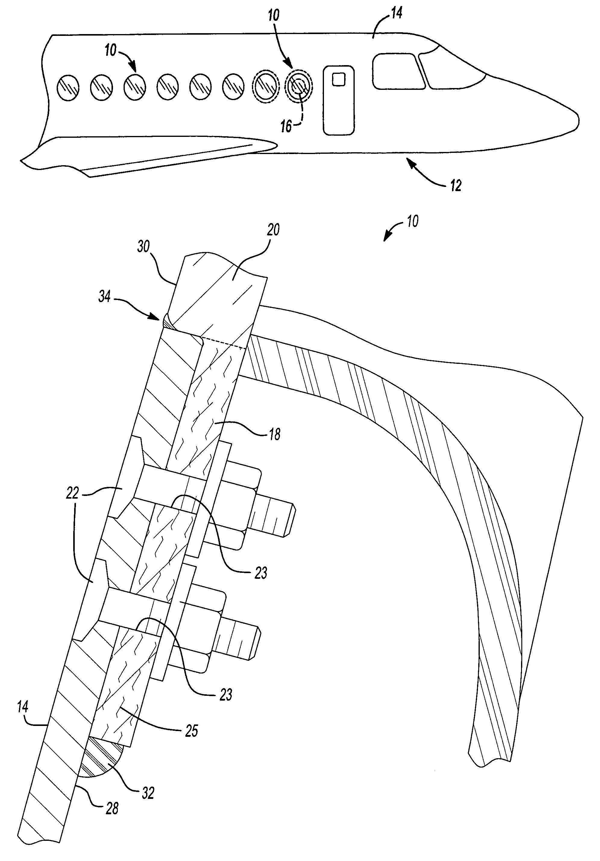
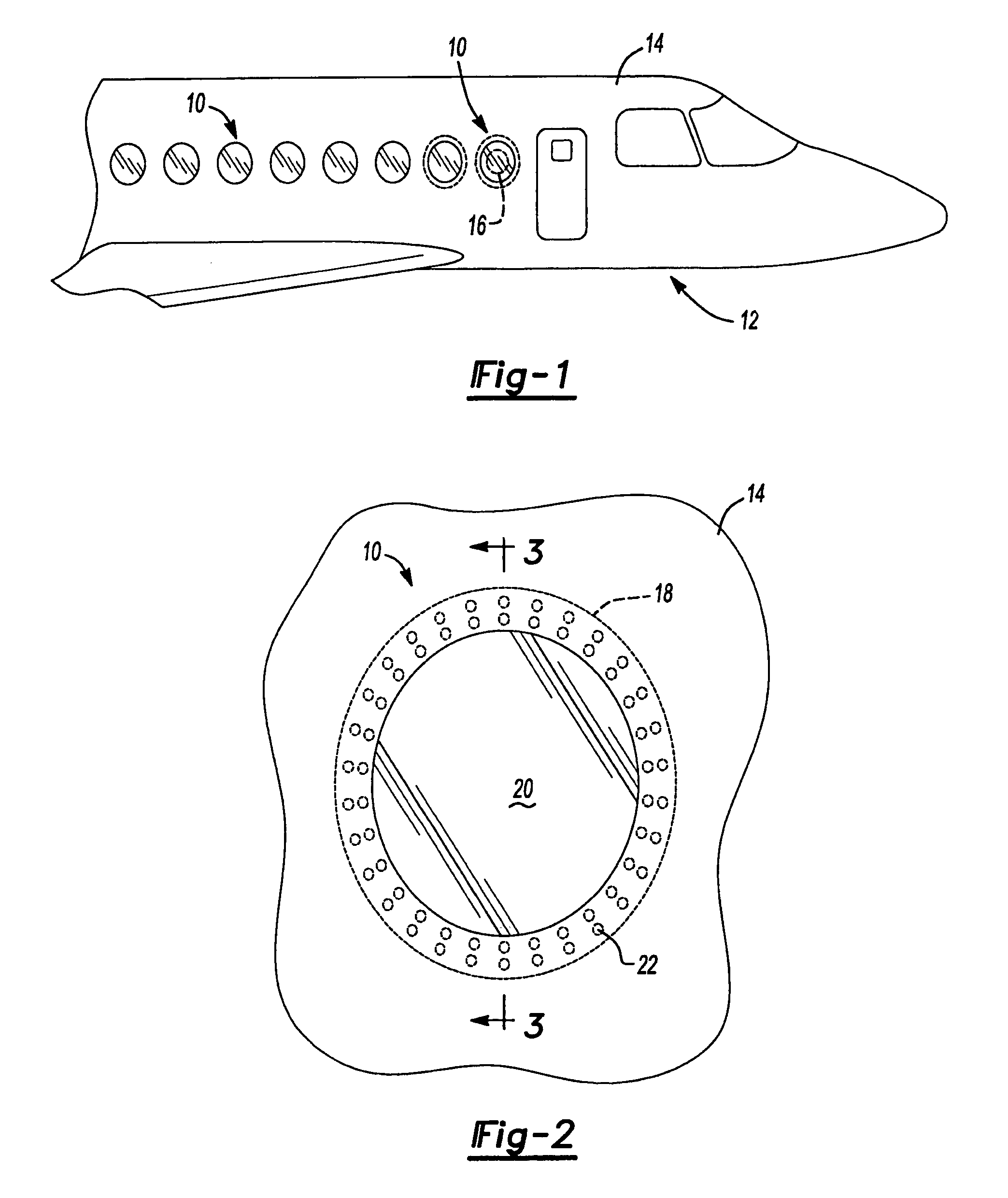
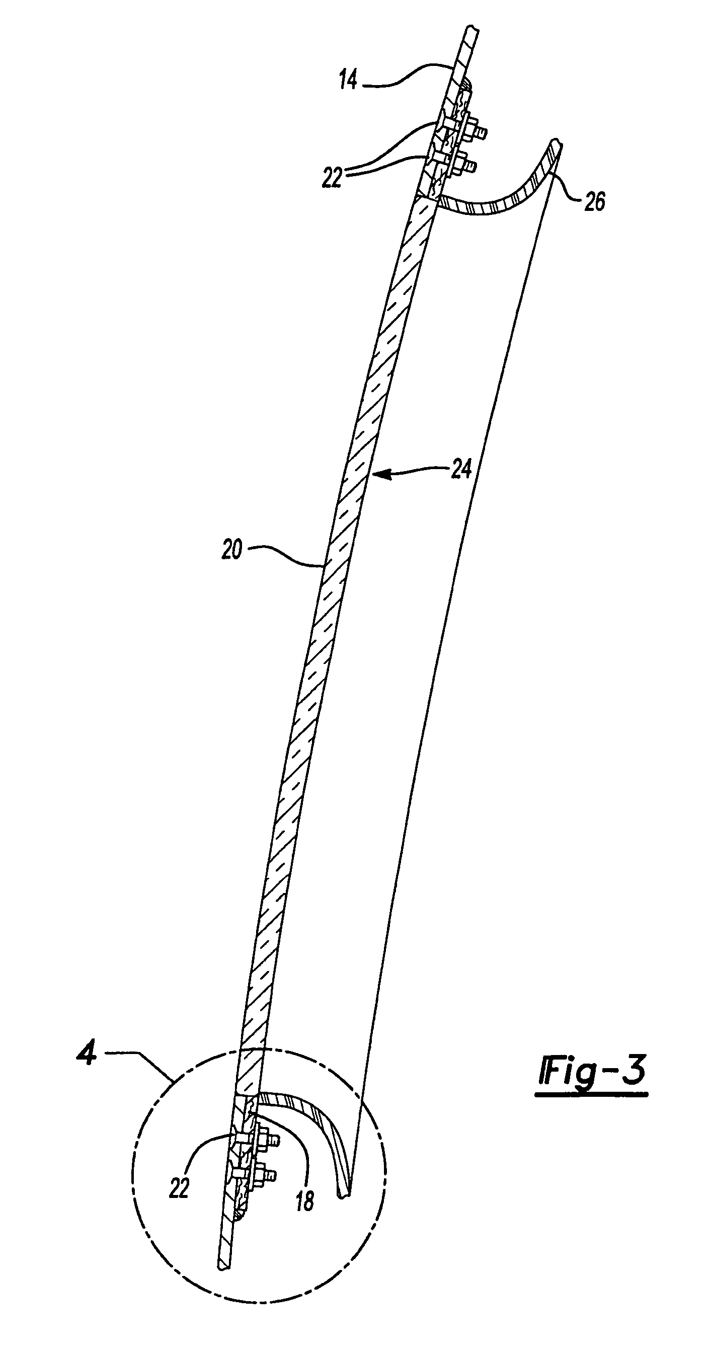
[0013]Referring to FIG. 1, there is illustrated a preferred embodiment of a load bearing window 10 constructed according to the principles of the present invention shown mounted to a mobile platform, in this instance, an exemplary aircraft 12. While in the particular example provided, the load bearing window 10 is shown as a side window of the aircraft 12. It should be appreciated, however, that the load bearing window 10 may be used in any portion of the aircraft 12 and may include the cockpit window or a door window. The aircraft 12 generally includes an airframe skin 14 that surrounds the load bearing window 10. A traditional prior art side window is shown in FIG. 1 in phantom lines and is generally indicated by reference numeral 16. As is apparent, the load bearing window 10 has a larger field of view than the tra...


PUM

PropertyMeasurementUnit
transparentaaaaaaaaaa
indices of refractionaaaaaaaaaa
sizeaaaaaaaaaa

Abstract

A substantially strong, lightweight load bearing window for use in a mobile platform, for example, an aircraft. The window includes a rim portion having a carbon reinforced resin structure and a transparent portion having a fiberglass reinforced resin structure. A plurality of holes are formed in the rim portion for enabling a plurality of connectors to be inserted therethrough. The rim portion has a smaller cross sectional area (i.e., thickness) than the transparent portion such that the rim portion is adapted to fit behind a skin of an aircraft, the transparent portion is adapted to be flush with the skin of the aircraft. The connectors fix the window to the skin of the aircraft. The window effectively forms a strong, structurally integral portion of the skin.

Description

FIELD OF THE INVENTION[0001]The present invention relates to aircraft windows, and more particularly to a load bearing window assembly for an aircraft.BACKGROUND OF THE INVENTION[0002]Passenger windows in most commercial aircraft are relatively small in size. This is due, in part, to the limited capabilities of current transparent window materials and also due to the heavy and complex support structure needed to support these windows within the frame of the aircraft.[0003]Typically, these transparent window materials consist of a transparent polymer. While very successful in the industry and exhibiting such useful qualities as high durability and easy formation of complex shapes, these polymer windows do have a limited strength capability. Moreover, these windows require a heavy support structure in order to support the window within the structural skin of the aircraft. This support structure generally includes window forgings and stringers. Each component is designed to strengthen ...

Claims


Application Information

Patent Timeline
Patent Type & Authority Patents(United States)
IPC IPC(8): B64C1/14B29C70/76B29C70/86B60J1/00
CPCB29C70/763B29C70/86B64C1/1484B64C1/1492Y02T50/433B29L2031/3082Y02T50/40
Inventor SALMON, JAMES J.MCKEE, SCOT
Owner THE BOEING CO
Why Eureka
Try Eureka