Tire carrier

a technology of tire carrier and carrier, which is applied in the direction of winding mechanism, curtain suspension device, hoisting equipment, etc., can solve the problems of spare tire not being properly located in the stowed position, difficulty for the operator to see the problem, and tire spare, etc., to achieve the effect of raising and lowering the carrier

Inactive Publication Date: 2006-04-18
DURA GLOBAL TECH
View PDF26 Cites 37 Cited by
  • Summary
  • Abstract
  • Description
  • Claims
  • Application Information

AI Technical Summary

Benefits of technology

[0011]According to another aspect of the present invention, a tire carrier assembly includes, in combination, a carrier adapted for supporting the spare tire and a winch having a flexible member operatively connected to the carrier and having one an actuation member to raise and lower the carrier. Means are provided for monitoring movement of the carrier from one position toward another position so that the spare tire is moved toward the another position and for providing a signal to prevent further movement of the carrier toward the another position when movement of the carrier produces a monitored condition having a predetermined level.

Problems solved by technology

While these prior tire carriers may adequately stow spare tires beneath motor vehicles under ordinary circumstances, several problems can arise.
For example, the spare tire may not be properly located in the stowed position and it is difficult for the operator to see the problem because the spare tire is located beneath the motor vehicle.
Additionally, even if the spare tire is properly stowed, the position of the spare tire can change over time such as, for example, due to cable stretching and it is difficult for the operator to see the problem since the spare tire is located below the motor vehicle.
Furthermore, the condition of the spare tire itself can change over time such as, for example, loosing inflation and it is difficult for the operator to see the problem since the spare tire is located below the vehicle.

Method used


Image

  • Tire carrier
  • Tire carrier
  • Tire carrier

Examples


Embodiment Construction

[0038]It will be apparent to those skilled in the art, that is, to those who have knowledge or experience in this area of technology, that many uses and design variations are possible for the improved tire carriers disclosed herein. The following detailed discussion of various alternative and preferred embodiments will illustrate the general principles of the invention with reference to tire carriers for a motor vehicle such as a truck, van, or sport utility vehicle (SUV). Other embodiments suitable for other applications will be apparent to those skilled in the art given the benefit of this disclosure such as for example for use with automobiles, recreational vehicles, trailers, off road vehicles such as dune buggies, industrial equipment, golf carts, and the like.

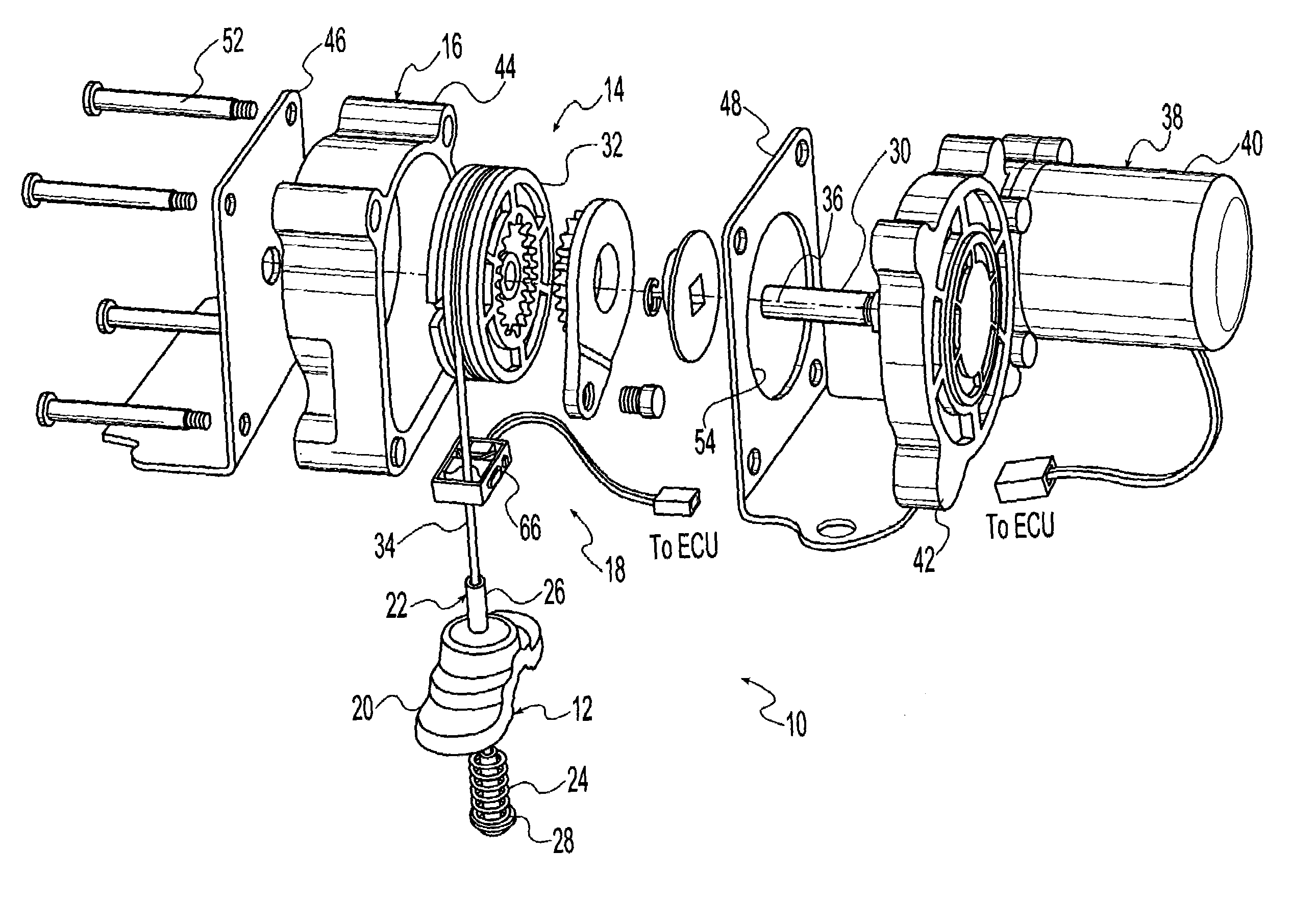
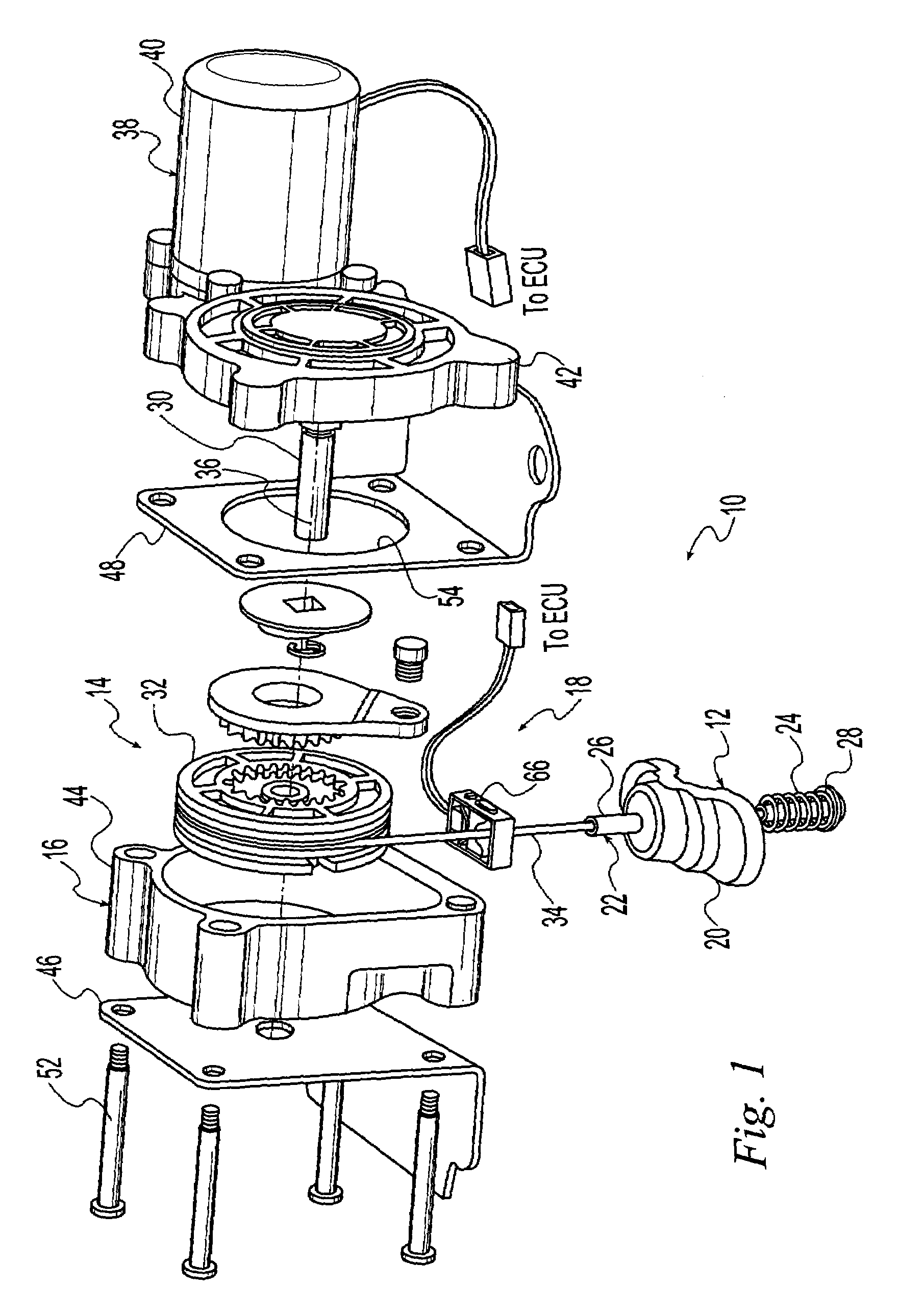
[0039]Referring now to the drawings, FIG. 1 shows a tire carrier assembly 10 according to a preferred embodiment of the present invention. The illustrated tire carrier assembly 10 includes a tire carrier 12 for carrying a...


PUM


Abstract

A tire carrier assembly for storing a spare tire on a vehicle which includes a carrier adapted for supporting the spare tire and a winch operatively connected to the carrier to raise and lower the carrier between a stowed position wherein the carrier is inaccessible and a deployed position wherein the carrier is accessible. The winch has a flexible member secured to the carrier and one of an electric motor and a manual device which selectively raises and lowers the carrier between the stowed and deployed positions. A monitoring device is located adjacent the winch and a control module is operably connected to the monitoring device to monitor movement of the carrier from the deployed position toward the stowed position.

Description

CROSS-REFERENCE TO RELATED APPLICATIONS[0001]This application claims the benefit of provisional patent application No. 60 / 429,843 filed on Nov. 27, 2002 and provisional patent application No. 60 / 441,496 filed on Jan. 21, 2003, the disclosures of which are expressly incorporated herein in their entirety by reference.STATEMENT REGARDING FEDERALLY SPONSORED RESEARCH[0002]Not ApplicableREFERENCE TO MICROFICHE APPENDIX[0003]Not ApplicableFIELD OF THE INVENTION[0004]The present invention generally relates to a tire carrier for a motor vehicle and, more particularly, to such a tire carrier which stores a spare tire beneath the motor vehicle.BACKGROUND OF THE INVENTION[0005]Vehicles with inflatable tires such as passenger cars, light and heavy duty trucks, tractor trailers, buses, commercial delivery vehicles, among other motorized forms of transportation and trailers pulled by such vehicles are conventionally equipped with spare tires. Some spare tires are stored under the vehicle using a ...

Claims


Application Information

Patent Timeline
Patent Type & Authority Patents(United States)
IPC IPC(8): B66D1/00A47H1/10B62D43/00
CPCB62D43/045
Inventor FLYNN, CHARLESPOSANI, MADHUWEITZEL, ROSANNETRUCKEY, JOHN
Owner DURA GLOBAL TECH
Why Eureka
Try Eureka