Roof ditch molding structure

Active Publication Date: 2006-04-18
NISSAN MOTOR CO LTD
View PDF11 Cites 41 Cited by
  • Summary
  • Abstract
  • Description
  • Claims
  • Application Information

AI Technical Summary

Benefits of technology

[0008]Accordingly, one object of the present invention is to provide a roof ditch molding str

Problems solved by technology

Thus, the overall size and weight of the roof ditch molding increase.
Also, since the roof ditch molding is fixedly coupled to the body panel of the vehicle by the clip that is fixedly coupled to both the roof ditch molding and the body panel, the clip cannot be utilized in a different vehicle that uses a dif

Method used


Image

  • Roof ditch molding structure
  • Roof ditch molding structure
  • Roof ditch molding structure

Examples


Embodiment Construction

[0031]Selected embodiments of the present invention will now be explained with reference to the drawings. It will be apparent to those skilled in the art from this disclosure that the following descriptions of the embodiments of the present invention are provided for illustration only and not for the purpose of limiting the invention as defined by the appended claims and their equivalents.

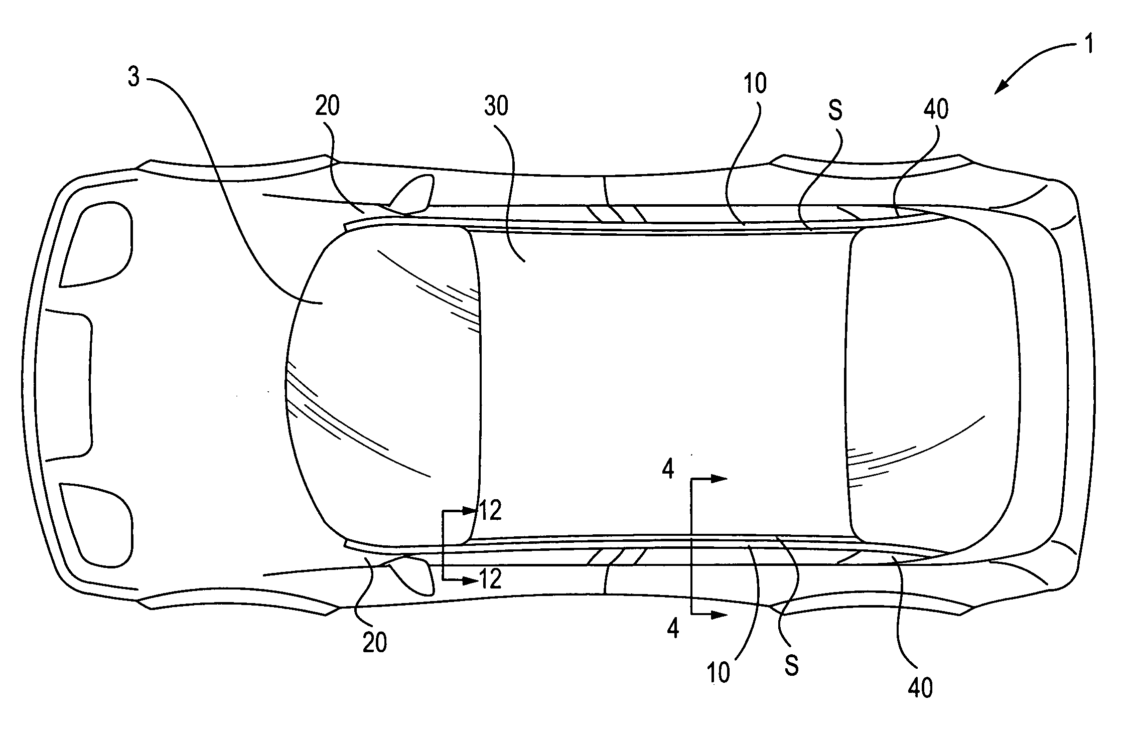
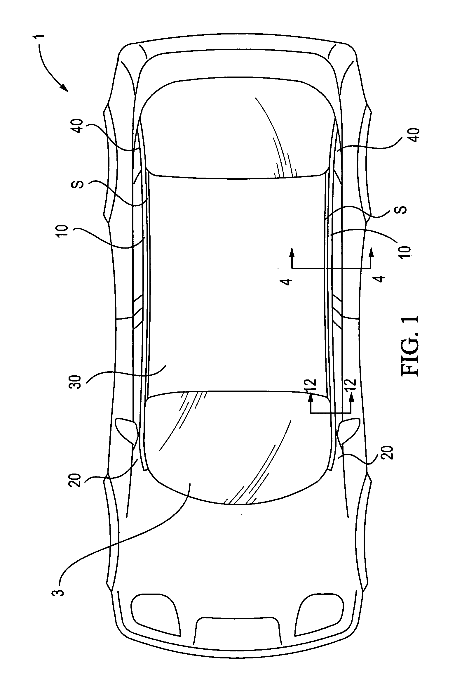
[0032]Referring initially to FIG. 1, a roof ditch molding structure of the present invention is illustrated in accordance with a preferred embodiment of the present invention. As seen in FIG. 1, a vehicle 1 is provided with a pair of roof ditch moldings 10 that extend in a generally longitudinal direction at left and right sides of the vehicle 1. More specifically, the left and right roof ditch moldings 10 preferably continuously extend from lower portions of left and right front pillars 20 along left and right side portions of a roof body member 30, to lower portions of left and right rear pillars...


PUM


Abstract

A roof ditch molding structure is provided with a body member having a drainage groove that receives a roof ditch molding which is preferably coupled thereto by a double sided tape formed of thermally cured urethane. The roof ditch molding has a rigid carrier member and a resilient cover member that substantially covers an outer surface of the carrier member. The rigid carrier member has a first transverse free end disposed between first and second vertical portions of the body member, and a second transverse free end disposed between the first transverse free end and the second vertical portion of the body member. The first transverse free end has a step portion extending substantially toward the second vertical portion of the body member. The cover member has first and second lip portions extending from the first and second transverse free ends of the carrier member, respectively, to form seals between the roof ditch molding and the drainage groove.

Description

BACKGROUND OF THE INVENTION[0001]1. Field of the Invention[0002]The present invention relates to a roof ditch molding structure. More specifically, the present invention relates to a roof ditch molding structure in which a roof ditch molding extending in a generally longitudinal direction of a vehicle is fixedly coupled to a body member and form a longitudinal water management channel on a lateral side portion of a roof of the vehicle.[0003]2. Background Information[0004]Japanese Laid-Open Patent Publication No. H11-70840 discloses a roof ditch molding structure in which a roof ditch molding extends in a longitudinal direction of a vehicle in a roof portion and a front pillar portion of the vehicle. In the roof ditch molding structure disclosed in this reference, the roof ditch molding in the roof portion of the vehicle is fixedly coupled to a body panel and a roof panel to form a longitudinal water drainage channel between the roof ditch molding and the roof panel. More specificall...

Claims


Application Information

Patent Timeline
IPC IPC(8): B60R27/00B60R99/00
CPCB60R13/04
Inventor OSTERBERG, GARYBLANCHARD, ROB
Owner NISSAN MOTOR CO LTD
Why Eureka
Try Eureka